Charged particle beam column

a charge particle and beam technology, applied in the direction of magnetic discharge control, instruments, heat measurement, etc., can solve the problems of affecting the integration the deformation of the resolution or displacement of the field of view which cannot be ignored, and the inability to affect the effect of the deflection uni

Active Publication Date: 2007-05-29
HITACHI HIGH-TECH CORP
View PDF11 Cites 39 Cited by
  • Summary
  • Abstract
  • Description
  • Claims
  • Application Information

AI Technical Summary

Benefits of technology

[0012]Moreover, according to the method of other related art (Japanese Patent Application Laid-Open No. 2001-15055), a Wiener filter disposed in front of an objective lens is used to disperse energy according to an angle by which a beam is tilted to such an extent that magnification chromatic aberration caused by the objective lens can be canceled. Thus, the blurring of an image derived from the magnification chromatic aberration is compensated. However, since the dispersion of energy caused by the Wiener filter occurs in a certain direction, this method can cope with the blurring occurring in the specific direction in which the beam is tilted. This is intended mainly to minimize the blurring of a spot by compensating magnification chromatic aberration caused by the objective lens and to thus prevent degradation of a resolution. However, when a beam is tilted at a large angle, the displacement of a field of view whose magnitude is as large as a sub micron diameter takes place at the same time because of spherical aberration or comatic aberration caused by the objective lens. Therefore, measures must be taken by electromagnetically shifting the beam.
[0013]Moreover, according to the method of other related art (U.S. Pat. No. 6,627,890), from the viewpoint of compensation of aberration, a means for preventing degradation of a resolution is adopted in order to convolute a quadrupole field or an octupole field to a charged particle beam in the vicinity of an objective lens where the charged particle is separated from an optical axis and compensation is achieved quite effectively, and to thus cancel chromatic aberration or spherical aberration caused by the objective lens in a direction corresponding to a certain direction of tilt in which the beam is tilted. However, there is spatial difficulty in incorporating a multipole field generating mechanism without affecting a field induced by an objective lens of a magnetic field immersion type or a high-resolution type that undergoes a decelerating electric field. This poses a problem in that the direction of tilt in which a charged particle beam is tilted is limited according to the direction of the quadrupole field or octupole field.
[0014]Accordingly, an object of the present invention is to provide a charged particle beam column that does not cause displacement of an image or degradation of a resolution of images despite a beam is tilted at a large angle.

Problems solved by technology

In the observation with a beam tilted at a large angle, the displacement or blurring of the spot of the beam causes degradation of a resolution or displacement of a field of view which cannot be ignored.
There is difficulty in incorporating the deflection unit without affecting the field induced by the objective lens of a magnetic field immersion type or a high-resolution type that undergoes a decelerating electric field.
However, since the dispersion of energy caused by the Wiener filter occurs in a certain direction, this method can cope with the blurring occurring in the specific direction in which the beam is tilted.
However, when a beam is tilted at a large angle, the displacement of a field of view whose magnitude is as large as a sub micron diameter takes place at the same time because of spherical aberration or comatic aberration caused by the objective lens.

Method used


Image

  • Charged particle beam column
  • Charged particle beam column
  • Charged particle beam column

Examples


first embodiment

[0029](First Embodiment)

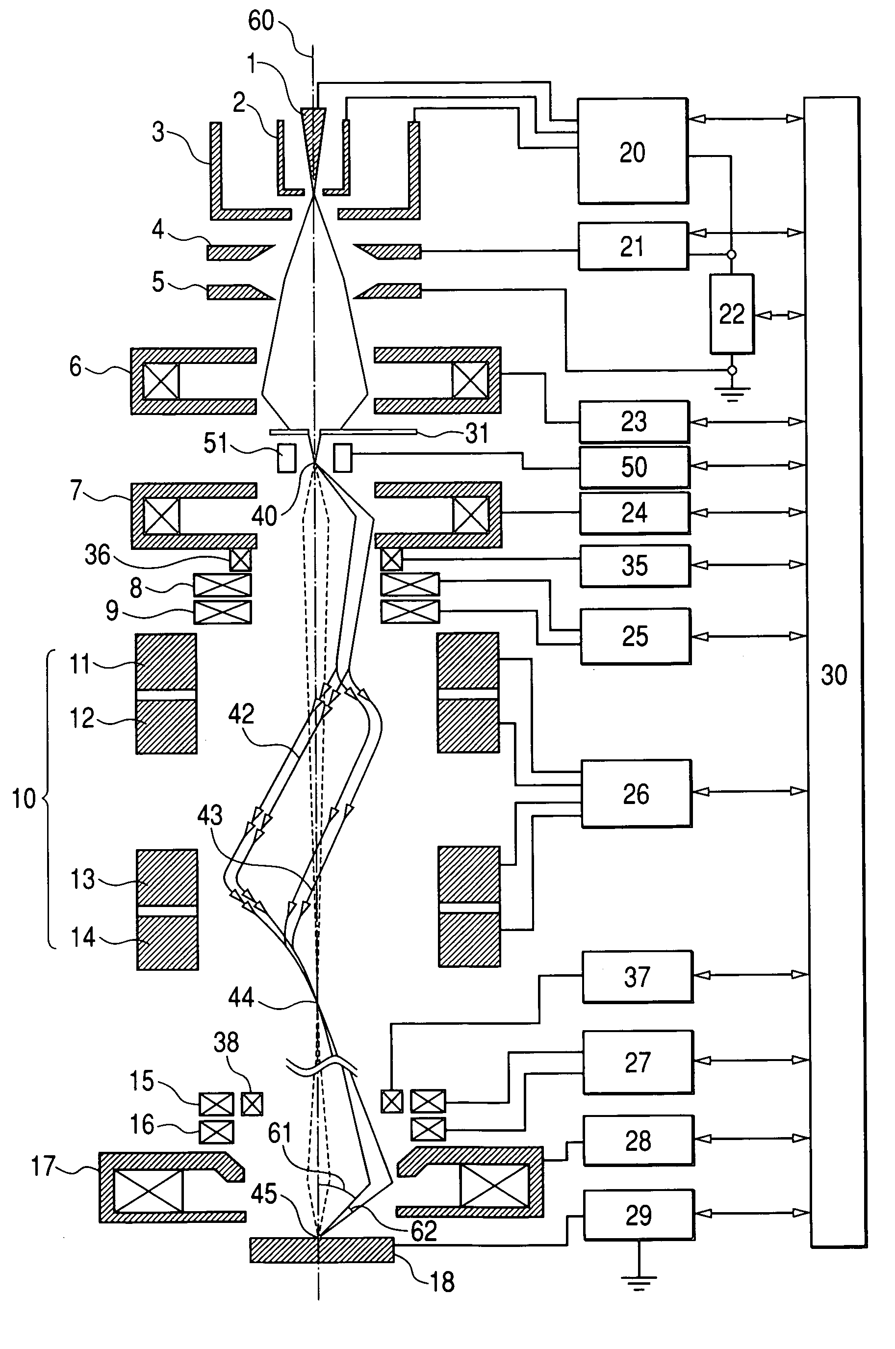
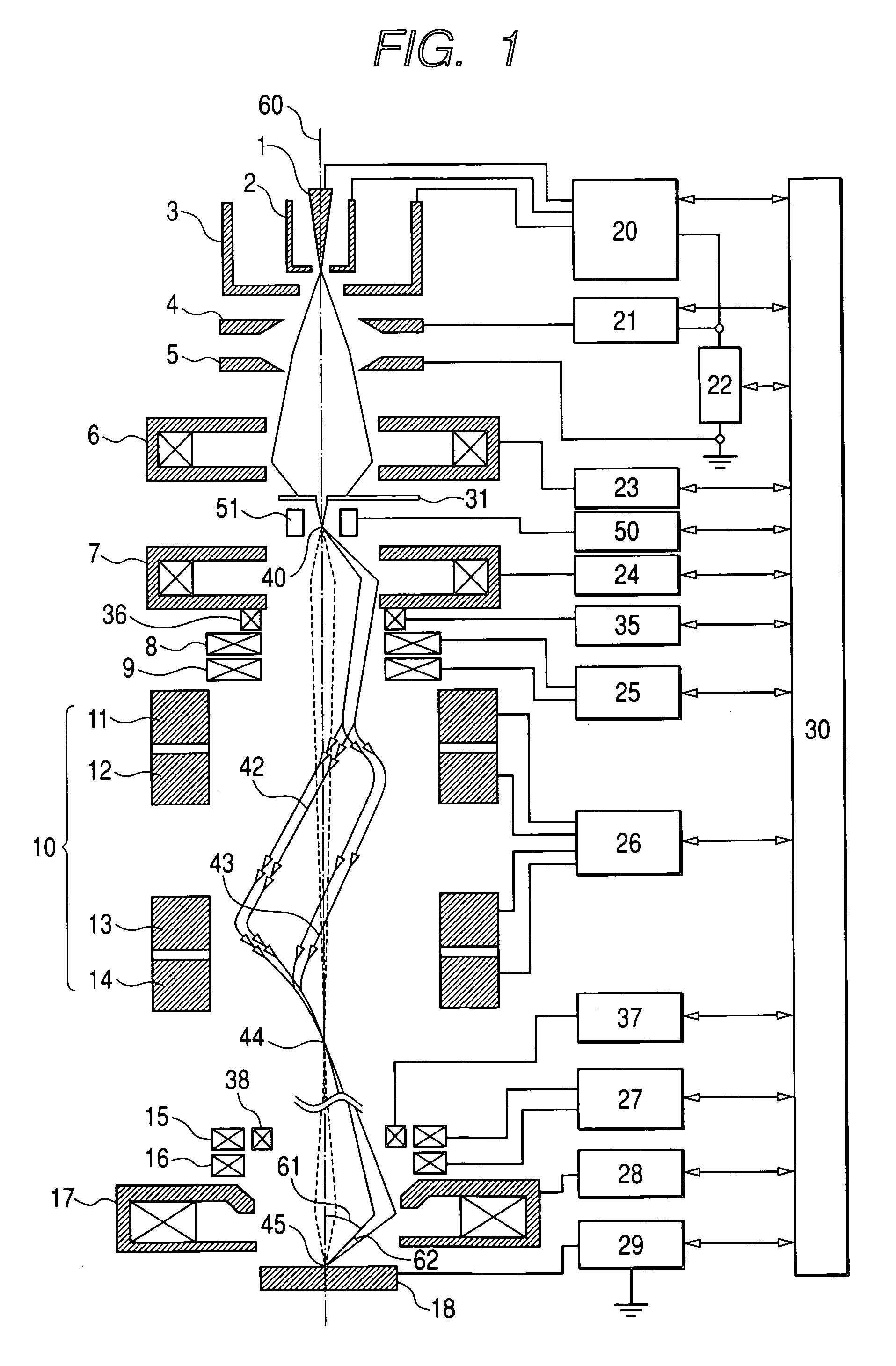
[0030]FIG. 1 shows the outline configuration of an electron beam column in accordance with the first embodiment of the present invention and the trajectories of an electron beam.

[0031]A Schottky emitter 1 is an electron source that has oxygen and zirconium diffused into a tungsten single crystal and makes the most of the Schottky effect. A suppressor electrode 2 and an extraction electrode 3 are located near the Schottky emitter 1. The Schottky emitter 1 is heated and a voltage of about +2 kV is applied to the Schottky emitter 1 and the extraction electrode 3, whereby the Schottky emitter 1 radiates electrons due to the Schottky effect. A negative voltage is applied to the suppressor electrode 2 in order to suppress electrons radiated from any place other than the distal end of the Schottky emitter 1. Electrons coming out of the opening of the extraction electrode 3 are accelerated and converged by an electrostatic lens composed of a first anode 4 and a secon...

second embodiment

[0042](Second Embodiment)

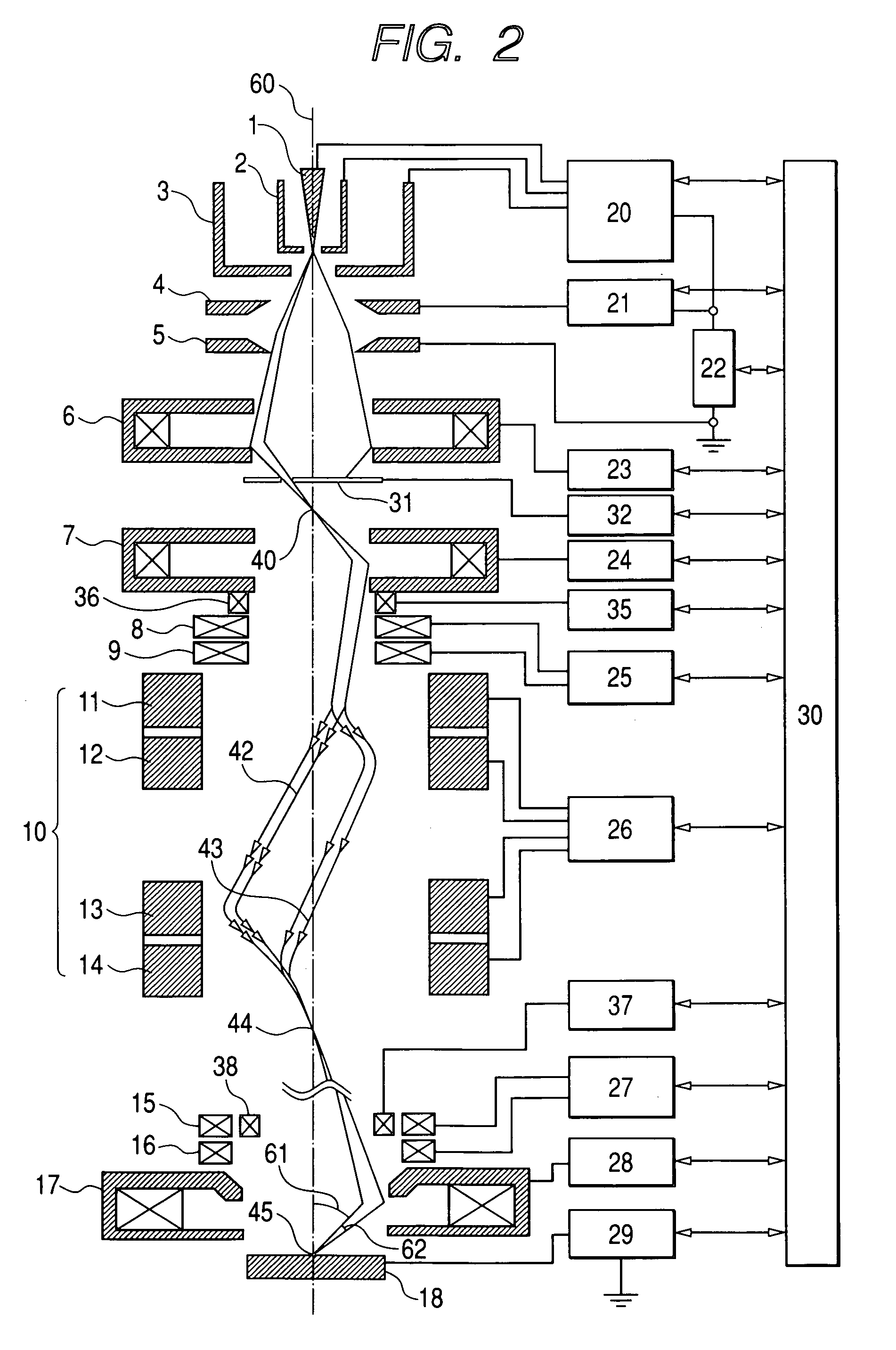
[0043]FIG. 2 shows the outline configuration of the second embodiment of the present invention and trajectories of an electron beam.

[0044]The present embodiment does not include the deflector 51 included in the first embodiment shown in FIG. 1 but includes: a movable aperture 31 that limits the incident position of a charged particle beam entering the aberration corrector 10 and the quantity of the incident beam; and a control means for controlling the movable aperture 31 so as to modify the direction of emission from the object point 44 of the objective lens without shifting the object point 44 of the objective lens that lies on the optical axis, and that thus routes the charged particle beam to the objective lens 17. Thus, the charged particle beam is tilted and converged on the surface of a specimen at a predetermined angle.

[0045]In the drawing, a two-dimensional position control mechanism 32 moves the movable aperture 31 to a desired position on a plane ...

third embodiment

[0047](Third Embodiment)

[0048]FIG. 4 shows the configuration of the major portion of a CD-SEM (length measuring scanning electron microscope), to which the present invention is adapted, as the third embodiment of the present invention.

[0049]The CD-SEM comprises a chamber 90 the interior of which is deaerated to enter a vacuum, a computer 30, and various control power supplies (20 to 29, 35, 37, 50, 74, 75, and 81) to be controlled by the computer 30, an image processing unit 76, a monitor 77, and an auxiliary chamber (not shown) to be used to carry a specimen to the chamber 90. In addition to the electron beam column including the aberration corrector and being shown in FIG. 1, a mechanism for detecting secondary electrons that are generated when an electron beam is irradiated to a specimen and a specimen stage to be used to carry or move a specimen are incorporated in the chamber 90. A focused spot 45 of an electron beam is swept using the scanning deflectors 15 and 16 in order to ...


PUM


Abstract

The present invention provides a charged particle beam column that does not cause displacement of an image or degradation of a resolution of images when a charged particle beam is tilted at a large angle. In the charged particle beam column including an aberration corrector, a deflector is used to control the direction of incidence of the charged particle beam on a second condenser lens but the object point of a condenser lens is not shifted. Consequently, the converging charged particle beam is tilted at a large angle with respect to the surface of a specimen without the necessity of shifting the object point of an objective lens lying on the optical axis of the charged particle beam column. At this time, the aberration corrector prevents a shift of an image or degradation of a resolution derived from the tilt of the charged particle beam.

Description

CLAIM OF PRIORITY[0001]The present invention claims priority from Japanese Application JP 2004-233286 filed on Aug. 10, 2004, the content of which is hereby incorporated by reference to this application.FIELD OF THE INVENTION[0002]The present invention relates to a charged particle beam technology, or more particularly, to a charged particle beam column adaptable to inspection / analysis equipment or machining equipment that irradiates a converging charged particle beam to the surface of a specimen.BACKGROUND OF THE INVENTION[0003]When a charged particle beam scanning microscope such as a scanning electron microscope (SEM) is used to measure the fine three-dimensional shape of the surface of a pattern of semiconductors, a charged particle beam must be obliquely routed to a specimen. The specimen is scanned in a plurality of directions with beams whose incidence angles are largely different from one another. Pieces of information on the height and slope of the surface of the specimen a...

Claims


Application Information

Patent Timeline
Patent Type & Authority Patents(United States)
IPC IPC(8): H01J3/14H01J37/28
CPCH01J37/1478H01J37/153H01J2237/0458H01J2237/1534H01J2237/2611H01J2237/2809H01J2237/2817
Inventor KAWASAKI, TAKESHIYOSHIDA, TAKAHONAKANO, TOMONORI
Owner HITACHI HIGH-TECH CORP
Why Eureka
Try Eureka