Method of manufacturing a semiconductor device
a manufacturing method and semiconductor technology, applied in the direction of semiconductor devices, electrical appliances, transistors, etc., can solve the problems of inability to obtain desirable electric characteristics and fluctuation in grain size, and achieve the effect of high-level crystallinity
- Summary
- Abstract
- Description
- Claims
- Application Information
AI Technical Summary
Benefits of technology
Problems solved by technology
Method used
Image
Examples
embodiment 1
[0065]Embodiment 1 will describe a case in which an amorphous silicon film is formed by a sputtering apparatus and the film is subjected to laser annealing using an XeCl excimer laser and a YAG laser.
[0066]A 5 inch square Corning 1737 substrate with a thickness of 0.7 mm is prepared. A silicon oxynitride film with a thickness of 200 nm is formed on the substrate by using a plasma CVD apparatus. Then a sputtering apparatus is used to form an amorphous silicon film on the surface of the silicon oxynitride film to a thickness of 50 nm.
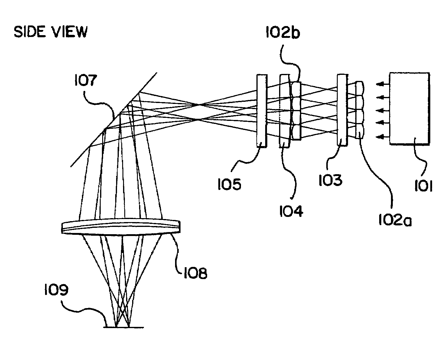
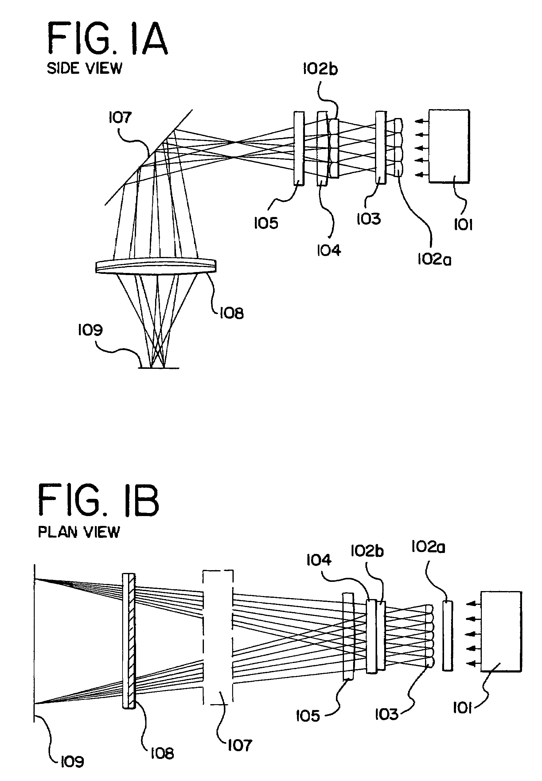
[0067]Thereafter, the XeCl excimer laser L3308 (wavelength: 308 nm, pulse width: 30 ns) manufactured by Lamda Physik, Inc. is used for laser annealing. This laser emitter emits a pulse oscillation laser and is capable of outputting an energy of 500 mJ / pulse. The size of the laser beam is 10×30 mm (both are half-width in the beam profile) at its exit. The laser beam emitted from the XeCl excimer laser is processed by an optical system as the one shown in F...
embodiment 2
[0070]A description given in Embodiment 2 is a case in which an amorphous silicon film is formed by a CVD apparatus and then subjected to heat treatment followed by laser annealing using an XeCl excimer laser and a second harmonic of a YAG laser.
[0071]A 5 inch square Corning 1737 substrate with a thickness of 0.7 mm is prepared. A silicon oxynitride film with a thickness of 200 nm is formed on the substrate by using a plasma CVD apparatus. Subsequently the same plasma CVD apparatus is used to form an amorphous silicon film on the surface of the silicon oxynitride film to a thickness of 50 nm. A solution containing an element that promotes crystallization is applied to the amorphous silicon film. When a nickel acetate solution, for instance, is used as the applied solution, the entire surface of the film is coated with the nickel acetate solution (with a weight percent of 10 ppm) by spin coating.
[0072]Next, the substrate is heated in nitrogen atmosphere at a temperature of 500° C. fo...
embodiment 3
[0074]Embodiment 3 gives a description of a case where heat treatment is conducted before laser annealing using a KrF excimer laser and a second harmonic of a YAG laser.
[0075]Through the same method as Embodiment 2, a silicon oxynitride film and an amorphous silicon film are formed and the amorphous silicon film is coated with a solution containing an element that promotes crystallization. Then the substrate is heated in nitrogen atmosphere at a temperature of 500° C. for an hour and further heated in nitrogen atmosphere at 550° C. for four hours.
[0076]Thereafter, the substrate is annealed with a KrF excimer laser having a wavelength of 248 nm by using an optical system as the one shown in FIGS. 1A and 1B. From FIG. 3, it is found that the absorption coefficient of a KrF excimer laser whose wavelength is 248 nm is 1.64×106 cm−1 and 1.86×106 cm−1 for an amorphous silicon film and for a polycrystalline silicon film, respectively. Therefore a KrF excimer laser is absorbed in an amorpho...
PUM
 Abstract
Description
Claims
Application Information
 - R&D
- Intellectual Property
- Life Sciences
- Materials
- Tech Scout
- Unparalleled Data Quality
- Higher Quality Content
- 60% Fewer Hallucinations
Browse by: Latest US Patents, China's latest patents, Technical Efficacy Thesaurus, Application Domain, Technology Topic, Popular Technical Reports.
© 2025 PatSnap. All rights reserved.Legal|Privacy policy|Modern Slavery Act Transparency Statement|Sitemap|About US| Contact US: help@patsnap.com


