Charged droplet sprayers

a technology of sprayer and droplet, which is applied in the direction of instruments, membranes, separation processes, etc., can solve the problems of interference peak in the acquired mass spectrum, and achieve the effect of optimizing the spray performance and increasing the performan

Active Publication Date: 2007-06-19
PERKINELMER U S LLC
View PDF12 Cites 32 Cited by
  • Summary
  • Abstract
  • Description
  • Claims
  • Application Information

AI Technical Summary

Benefits of technology

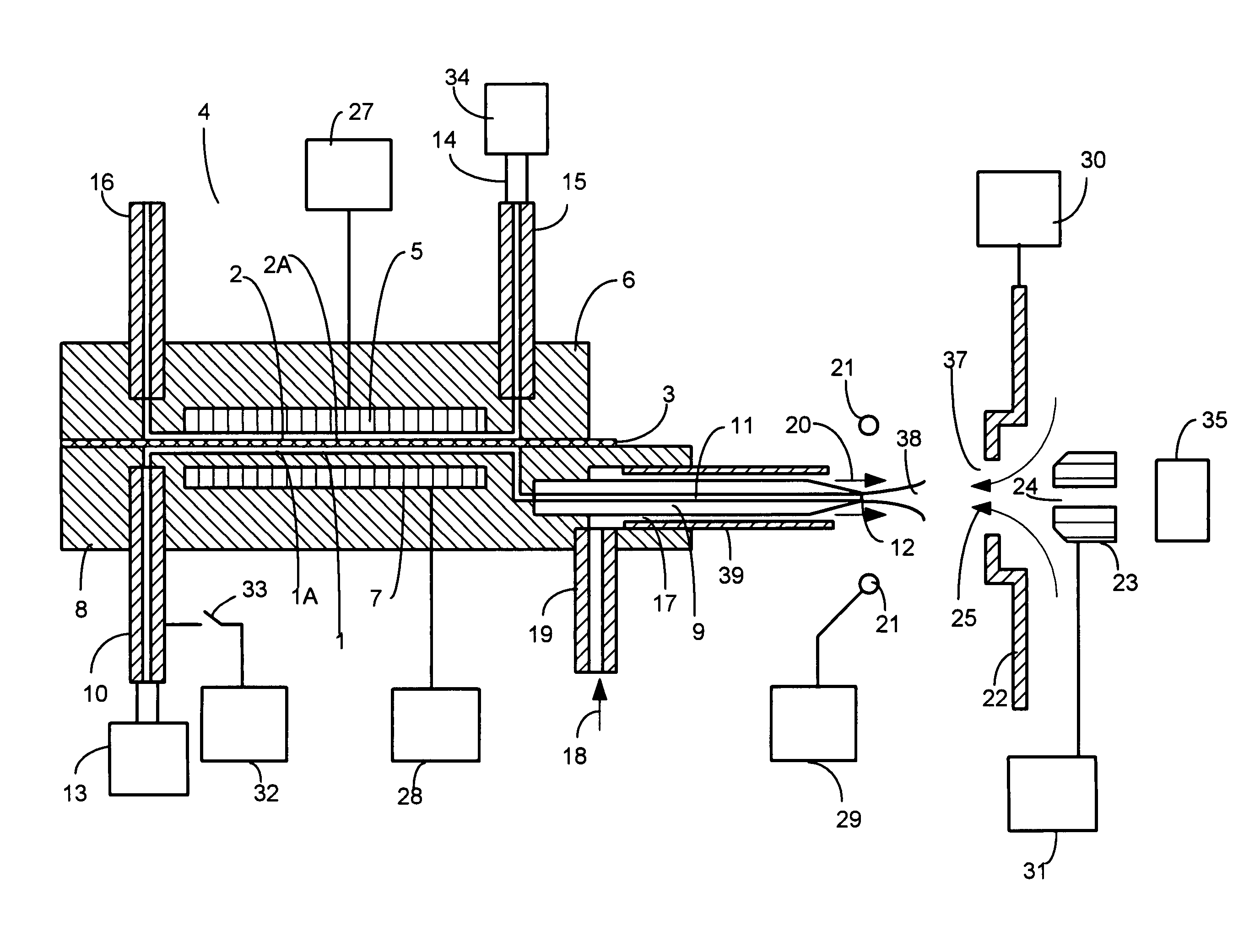
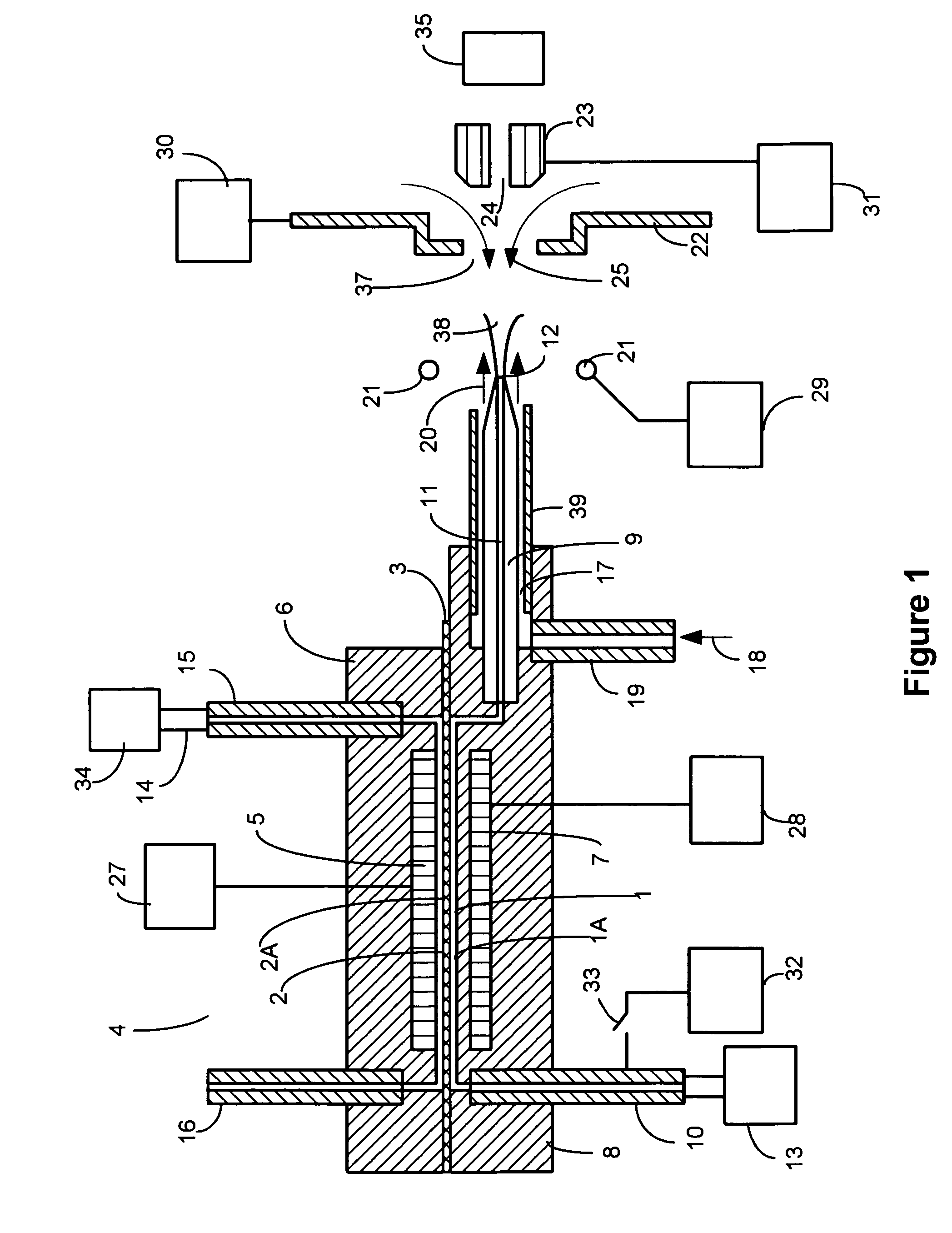
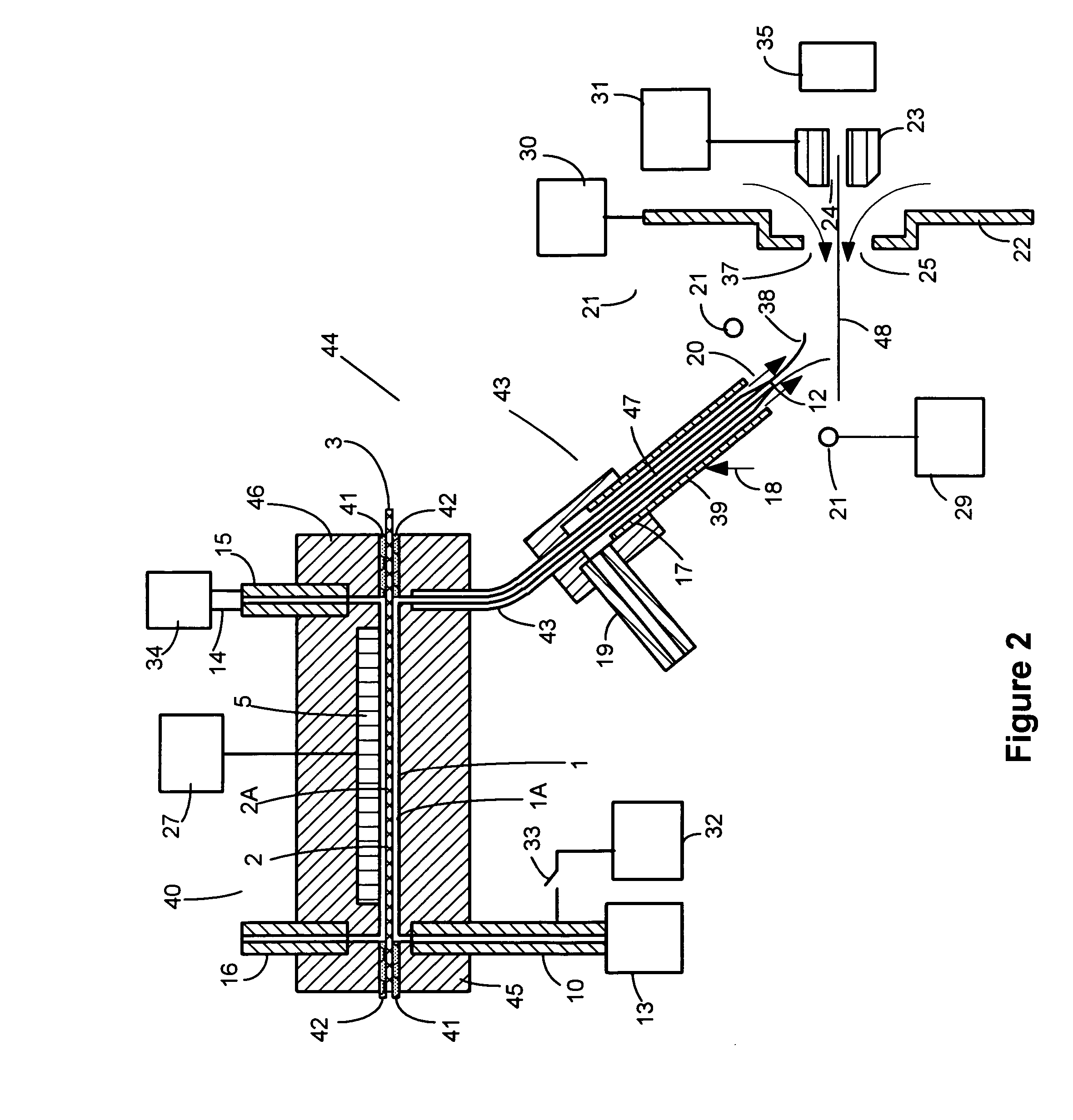
[0011]The invention comprises embodiments of charged droplet sprayers that provide increased performance and the ability to optimize charged droplet spray performance over a range of operating conditions and applications. In one embodiment of the invention, the charged droplet sprayer comprises a first and a second solution flow channel separated by a single or layered semipermeable dielectric membrane. Selected charged species are transferred into or removed from the first solution through the membrane creating a net increase in one polarity charge in the first solution flow during charged droplet spraying. The first solution, with an increase in one charge polarity, forms a spray of charged droplets at one or more first solution flow channel exit tips. The transfer of charged species through the membrane and the production of the charged droplets from the first solution flow channel exit tip are driven by the Electrospray electric field maintained at the first solution flow channel exit tip. The membrane and the first and second solutions form electrically resistive conduits between the Electrospray electric field present at the first solution flow channel exit tip and an electrode surface positioned in the second solution flow channel in contact with the second solution. The Electrospray electric field maintained at the first solution flow channel exit tip is established by the relative electrical potentials applied to counter electrodes spaced from the exit tip and the electrical potential applied to the electrode in contact with the second solution in the second solution flow channel. The charged species transferred into or removed from the first solution flow through the membrane is determined by selection of the membrane composition, composition of the second solution electrode, composition and flow rates of the first and second solutions and the polarity of the electric field across the membrane. Positive and negative polarity charged droplet spray current can be optimized for a given application by adjusting the variables of solution chemistries and flow rates, relative electrical potentials applied to electrodes and by the selection of membrane materials. Total Electrospray current can be changed during Electrospray ionization by changing the second solution composition and / or first solution flow rate.
[0012]Protons can be transferred from the second solution into aqueous sample solutions to increase solution charge and decrease solution pH during positive polarity charged droplet spraying without adding acid species directly to the first solution. Redox reactions occur at conductive electrode surfaces positioned in one or more second solution flow channels driven by the Electrospray electric field. The same electric field drives the charged species across the membrane between the first and second solutions. Deposition of anions on first solution flow channel conductive surfaces is minimized or eliminated during positive ion polarity Electrospray. This avoids deplating of anions from conductive surfaces in the sample solution flow path when the Electrospray ion polarity is reversed. The interference anions produced by deplating from conductive surfaces in negative polarity ES can result in charge suppression of analyte species and the occurrence of unwanted contamination peaks in acquired mass spectra. The converse holds when switching from negative to positive polarity Electrospray ionization. In analytical applications requiring upstream sample separation techniques such as in LC / ES / MSn analysis, conductive surfaces cannot be entirely eliminated in upstream sample solution flow paths due to the presence of upstream LC columns, valves, fittings and pumps. In such cases, the voltage applied to the electrode in contact with the second solution can be adjusted to minimize or eliminate the occurrence of redox reactions on upstream conductive surfaces in the sample solution flow channel. Embodiments of the invention enable the generation of charged droplet sprays in which the total Electrospray or charged droplet spray current produced is greater than the electrical current generated due to reduction or oxidation reactions occurring on conductive surfaces in the first solution flow channel. In charged droplet sprayers configured according to the invention, redox reactions supplying electrical current to the charged droplet formation process in Electrospray occur on electrode surfaces configured external to the first solution flow channel.
[0013]In alternative embodiments of the invention, charged droplet sprayers can be configured with the first solution separated from multiple second solutions by individual membranes comprised of similar or different materials. Different charged species can be individually or simultaneously added to and / or removed from the first solution during charged droplet spraying using multiple membrane embodiments. The first solution flow channel may be configured to terminate with single or multiple exit tips. Generating multiple charged droplet sprays from multiple exit tips allows an increase in the total charged droplet spray current produced for a given first solution composition and allows optimization of the overall charged droplet spray geometry for specific applications. Charged droplet sprays with single or multiple exit tips can be formed using unassisted Electrospray or pneumatic nebulization of solution in the presence of an electric field, alternatively described as Electrospray with pneumatic nebulization assist.
[0014]An alternative embodiment of the invention comprises first and second solution flow channels separated by a semipermeable dielectric membrane configured with an insulated porous electrode positioned adjacent to the first solution side of the membrane or configured between membrane layers. The electric field formed between the insulated porous membrane and the electrode configured to be in contact with the second solution in the second solution flow channel can be adjusted to increase or decrease charge species transfer through the membrane. The addition of the insulated porous membrane allows additional control of charged species transfer into or out of the first solution without the need to adjust solution chemistry in the first or second solutions during charged droplet spraying. The charged droplet sprayer can be configured with multiple second solution flow channels separated from the first solution by separate membranes. Conversely, the charged droplet sprayer can be configured with multiple first solution channels separated from a second solution flow channel by separate membranes. The multiple first solution flow channel configuration allows the simultaneous spraying of positive and negative polarity charged droplets from two sprayer exit tips using the same or different first solutions. Alternately, charged droplet sprays of the same polarity may be generated from the two sprayer tips from different first solutions.
[0015]An alternative embodiment of the invention comprises a single first solution flow channel configured with two exit tips with only dielectric surfaces or no connected conductive surfaces present in the first solution flow channel where reduction or oxidation (redox) reactions can occur. Opposite polarity charged droplets of the first solution are sprayed simultaneously from the two exit tips toward counter electrodes having different electrical potentials applied. Such dual output, dual polarity charged droplet sprayer may be combined with the membrane separated first and second solution flow channel sprayer embodiment described above to allow addition or removal of one charged species to the first solution through the membrane and bifurcation of charge species in the first solution flow path during charged droplet spraying. Using such combined charged droplet sprayer configuration, the total charged droplet spray current of opposite polarity may not be equal from both tips. Such current balance can be adjusted by selecting the appropriate relative electrical potentials applied to electrodes. One of the two exit tips may be positioned sufficiently close to a counter electrode such that solution leaving the exit tip forms an electrical contact with the counter electrode without spraying. Using this embodiment, separation of charge in the first solution can be achieved during charged droplet spraying while avoiding redox reactions on surfaces in the first solution flow channel and without the need to optimize two charged droplet sprays simultaneously. Finer control of the remaining single charged droplet spray can be achieved by adjusting solution chemistry or applied voltages using such dual outlet embodiment employing solution contact to the counter electrode. Alternatively, such a second solution channel may be terminated with an end electrode allowing electrical contact with the first sample solution removed from the first solution flow path while preventing loss of sample solution flow to the electrode.
[0016]In an alternative embodiment of the invention, the first sample solution composition may be modified during charged droplet spraying through a liquid junction configured between a first and second solution flow channel of a dual output opposite polarity charged droplet sprayer embodiment. The geometry of the liquid junction between both solutions can be configured to maximize or minimize contact between the two solutions while allowing exchange of charged species. The dual flow channel charged droplet sprayer embodiment may be configured and operated to prevent flow of the first solution into the second solution flow channel, allow flow of the first solution into the second solution or vice versa, during charged droplet spraying. As described above, to simplify optimization and control of charged droplet spraying from one exit tip, the second flow channel exit tip can be positioned sufficiently close to a counter electrode such that the liquid leaving the exit tip forms an electrical contact with the counter electrode. Charged droplet spray can be generated from the first solution flow channel exit tip using Electrospray or Electrospray with pneumatic nebulization assist. Embodiments of the invention may be combined to allow more flexibility and range in controlling the charged droplet spray process. Increased control of the charged droplet formation process and the sample solution composition during Electrospray ionization allows enhancement and optimization of ES / MSn and LC / ES / MSn performance for given applications. Charged droplet spraying can be conducted using the embodiments of the invention or using combinations of embodiments of charged droplet sprayer devices configured according to the invention whereby the charged droplet spray current produced is greater than the electrical current generated due to redox reactions occurring on conductive surfaces in the first solution flow channel.

Problems solved by technology

Simultaneous Electrospraying of a sample solution from positive and negative sprays partitions the sample species in a manner that may not be readily predictable or controlled.
The contamination ions occurring in mass spectra when polarity is changed can reduce sample signal due to charge competition and cause interference peaks in the acquired mass spectrum.

Method used


Image

  • Charged droplet sprayers
  • Charged droplet sprayers
  • Charged droplet sprayers

Examples


Embodiment Construction

[0045]Charged liquid droplets can be formed in charged droplet spray devices using unassisted Electrospray or pneumatic nebulization in the presence of an electric field. Charged droplet production in unassisted Electrospray requires the formation of a stable Taylor cone jet from the sample solution exiting a channel or tube in the presence of an electric field. The charged droplets form by separating from a liquid filament protruding from the tip of the Taylor cone. If a sample solution has high surface tension, it may not be possible to form a stable Taylor cone at atmospheric pressure where electrical potentials applied have an upper limit due to gas phase break down. If the conductivity of a sample solution is too high, the filament projecting from the Taylor cone may not separate into uniform charged droplets due to damping of the fluid column instability by charge movement within the solution. Stable Taylor cones are more difficult to sustain at higher liquid flow rates. Both ...


PUM

PropertyMeasurementUnit
molecular weightaaaaaaaaaa
electrical potentialaaaaaaaaaa
electrical potentialsaaaaaaaaaa

Abstract

Charged droplet spray is formed from a solution with all or a portion of the charged droplet spray current generated from reduction or oxidation (redox) reactions occurring on surfaces removed from the first or sample solution flow path. In one embodiment of the invention, two solution flow channels are separated by a semipermeable membrane. A first or sample solution flowing through the first solution flow channel exchanges cation or anion charged species through the semipermeable membrane with a second solution or gas flowing through the second flow channel. Charge exchange is driven by the electric field applied at the charged droplet sprayer sample solution outlet. Redox reactions occur at an electrode surface in contact with the second solution. The invention increases the control and range of the Electrospray ionization process during ES / MS operation. Alternative embodiments of the invention provide for conducting redox reactions on conductive surfaces removed from the first or sample solution flow path but not separated by semipermeable membranes.

Description

CROSS-REFERENCE TO RELATED APPLICATION[0001]This application claims priority to U.S. Provisional Application No. 60 / 573,666, filed on May 21, 2004, the disclosure of which is incorporated herein by reference in its entirety.FIELD OF THE INVENTION[0002]The invention relates to the production of charged liquid droplet sprays generated in Electrospray ionization sources interfaced to mass spectrometers.BACKGROUND OF THE INVENTION[0003]Sprays of charged liquid droplets can be produced through Electrospray and pneumatic nebulization or ultrasonic nebulization in the presence of an electric field. The mechanisms of ion production from unassisted Electrospray ionization have been described by Karbarle, P., J. Mass Spectrom. 35, 804-817 (2000)[1], and Karbarle, P. and Ho, Y. “Electrospray Ionization Mass Spectrometry”, Edited by Richard Cole, Chapter 1, 3-63, 1997[2]. The oxidation and reduction chemical reactions that occur, or that can be induced to occur, on conductive surfaces located i...

Claims


Application Information

Patent Timeline
Patent Type & Authority Patents(United States)
IPC IPC(8): B01D59/44G01N24/00H01J27/26H01J49/04H01J49/10H01J49/16
CPCB01D61/00B01D61/425H01J49/165H01J49/167H01J49/0018B01D2313/345G01N30/7266Y10T436/212Y10T436/24
Inventor WHITEHOUSE, CRAIG M.WHITE, THOMAS
Owner PERKINELMER U S LLC
Why Eureka
Try Eureka