System and method for providing a low jitter data receiver for serial links with a regulated single ended phase interpolator

a data receiver and interpolator technology, applied in pulse manipulation, pulse technique, instruments, etc., can solve the problems of propagation delay, limitations of parallel bus structures, and limitations of parallel bus structures, and achieve the effect of low power supply transfer function

Active Publication Date: 2007-06-19
NAT SEMICON CORP
View PDF13 Cites 13 Cited by
  • Summary
  • Abstract
  • Description
  • Claims
  • Application Information

AI Technical Summary

Benefits of technology

[0022]It is yet another object of the present invention to provide a system and method for providing a clock and data recovery circuit that has a low transfer function of power supply noise to sampling clock jitter.

Problems solved by technology

A central challenge in the design of digital systems is to provide reliable, error-free high speed communications between the various elements of a digital system.
However, as the speed of digital communications systems increases, parallel bus structures are becoming widely recognized as having limitations.
The limitations of parallel bus structures are due to the difference in propagation delay between the fastest line and the slowest line on a parallel bus.
For example, clock jitter may be due to residual error from the phase detection process.
Clock jitter may also be due to local oscillator noise.
Clock jitter may also be due to injected power supply noise.
CML D flip flop circuits, however, have a disadvantage because the CML circuitry consumes static power.
A second disadvantage of CML flip flop circuits is that their full differential output levels are not compatible with standard CMOS logic.

Method used


Image

  • System and method for providing a low jitter data receiver for serial links with a regulated single ended phase interpolator
  • System and method for providing a low jitter data receiver for serial links with a regulated single ended phase interpolator
  • System and method for providing a low jitter data receiver for serial links with a regulated single ended phase interpolator

Examples


Embodiment Construction

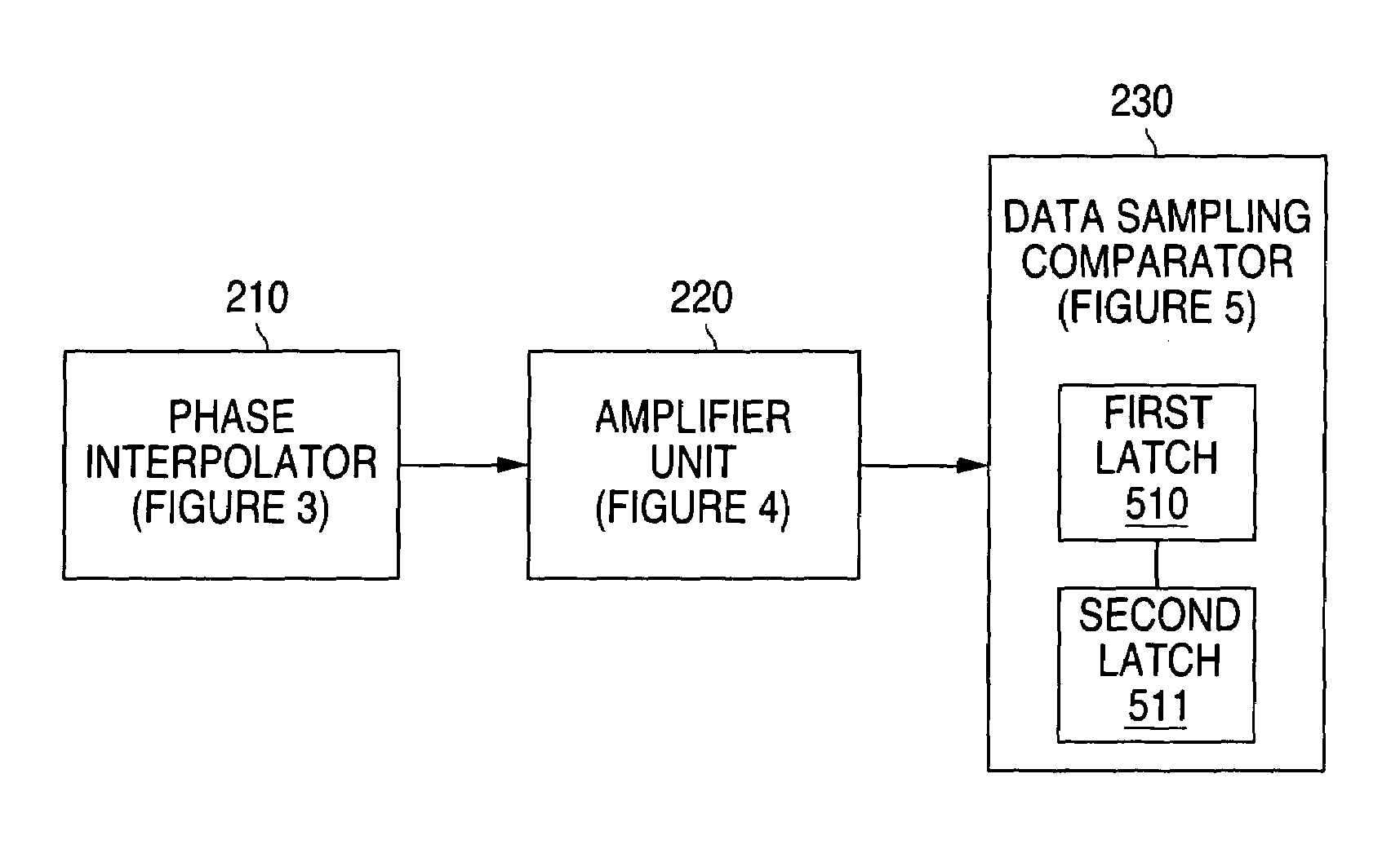
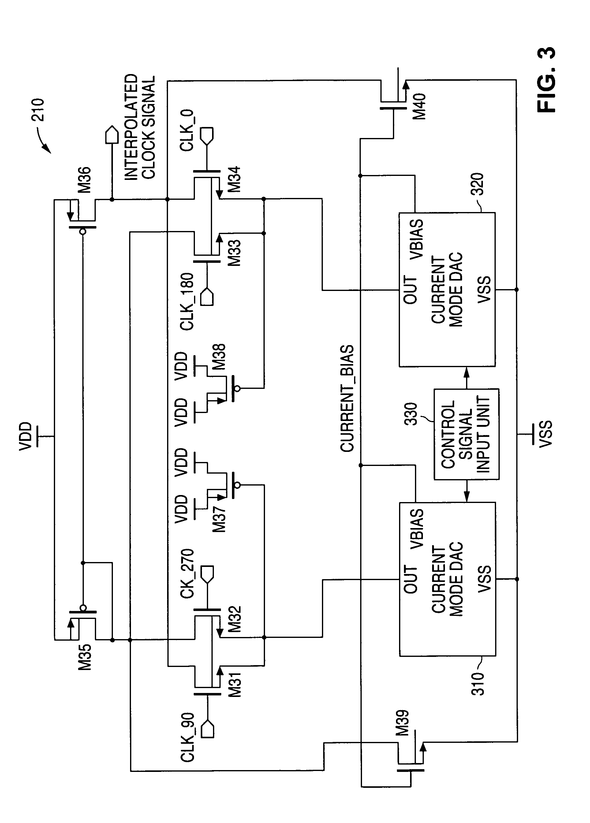
[0034]FIGS. 1 through 7B and the various embodiments used to describe the principles of the present invention in this patent document are by way of illustration only and should not be construed in any way to limit the scope of the invention. Those skilled in the art will understand that the principles of the present invention may be implemented in any type of suitably arranged clock and data recovery circuit.

[0035]To simplify the drawings the reference numerals from previous drawings will sometimes not be repeated for structures that have already been identified.

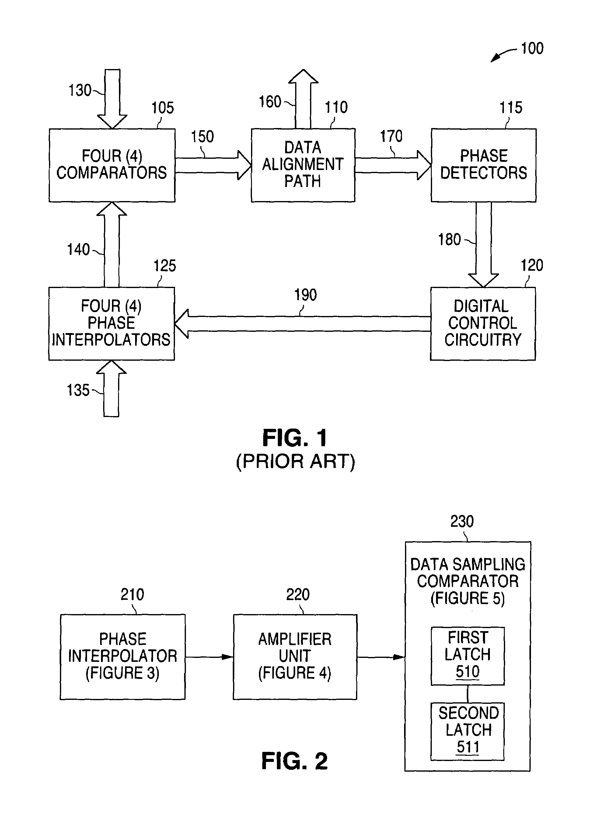
[0036]In order to better understand the principles of the present invention a description of a prior art clock and data recovery system will first be given. FIG. 1 illustrates a schematic diagram of a prior art clock and data recovery circuit 100 that employs phase interpolator architecture. The clock and data recovery circuit 100 requires four (4) clock phases that are generated by a phase locked loop (PLL) (not shown in FI...


PUM


Abstract

A system and method is disclosed for providing a clock and data recovery circuit that comprises a low jitter data receiver. The low jitter data receiver comprises a phase interpolator, an amplifier unit and a data sampling comparator. The phase interpolator and the amplifier unit provide the data sampling comparator with a single ended clock signal that is relatively immune to power supply noise. The data sampling comparator samples an input data stream with minimal jitter due to power supply noise. The data sampling comparator consumes less static power than a current mode logic D flip flop and also has output levels that are compatible with complementary metal oxide semiconductor (CMOS) logic.

Description

TECHNICAL FIELD OF THE INVENTION[0001]The present invention is generally directed to the manufacture of clock and data recovery circuits for semiconductor devices and, in particular, to a system and method for providing a low jitter data receiver using a regulated single ended phase interpolator.BACKGROUND OF THE INVENTION[0002]Digital systems usually contain several individual elements. For example, a personal computer may have a central processing unit (CPU), a graphics processing chip, memory units, and other types of components. A central challenge in the design of digital systems is to provide reliable, error-free high speed communications between the various elements of a digital system.[0003]High speed digital communications may be carried out by using either a parallel bus or a high speed serial bus. One example of a parallel bus is the Peripheral Component Interface (PCI) bus. The PCI bus is a parallel bus that is sixty four (64) bits wide and that is clocked at a speed of ...

Claims


Application Information

Patent Timeline
Patent Type & Authority Patents(United States)
IPC IPC(8): G11C7/00
CPCG11C7/02G11C7/1078G11C7/1087G11C7/109G11C7/22G11C7/222H03K3/356034H03K3/356086H03K5/003H03K5/082
Inventor LEWICKI, LAURENCE D.OBEIDAT, AMJAD T.NODENOT, NICOLAS
Owner NAT SEMICON CORP
Why Eureka
Try Eureka