Pyrolyzing gasification system and method of use

a gasification system and gasification method technology, applied in the direction of gasifier mechanical details, combustion types, sustainable manufacturing/processing, etc., can solve the problems of increased particulate emissions, loss of potentially valuable by-products of the process, and formation of corrosive slag, etc., to achieve superior control of ceramic heat exchangers, high gasifier discharge temperatures, and improved gasification

Inactive Publication Date: 2007-07-10
HEAT TRANSFER INT
View PDF7 Cites 25 Cited by
  • Summary
  • Abstract
  • Description
  • Claims
  • Application Information

AI Technical Summary

Benefits of technology

[0015]The inventive gasifier provides controlled air injection into the feed cone portion, on each surface of the fuel hopper, and when required, through and around the ash removal assembly at the bottom of the fuel hopper. Air injection is achieved using independently controlled manifolds via ceramic tuyeres, using independently controlled air injection lances which extend radially through the fuel pile, or using a combination of tuyeres and lances. The air injection design allows air flow in one cell to be adjusted independently of air flow in other cells, and allows air flow in an area of a given cell to be adjusted independently of the air flow in other areas of the same cell. The injected air may be continuous or pulsed. Pulsed air is advantageous because it reduces clinker formation.
[0034]The method of pyrolyzing solid fuels such as non uniform wastes to obtain useable ash and recover heat energy has several novel features: The gasifier is all ceramic and operates in starved air conditions within which air flow is provided in strict control. Acidic combustion gas from the gasifier is processed within an all-ceramic, uniquely staged oxidizer where combustion is maintained at relatively low temperatures to produce a clean flue gas having low NOx, and having VOC, hydrocarbons, and CO at levels that are well below code. Energy recovery is accomplished using an all-ceramic heat exchanger or conventional methods of energy recovery such as boilers. The method of pyrolyzing non uniform solid wastes can produce a useful ash for use as a fertilizer both in direct application to and as a feed stock for fertilizer production. By reducing the solid wastes to ash form, enormous waste volume reduction is achieved. For example, pyrolysis of wood provides an approximate volume reduction of 98 percent, and pyrolysis of poultry litter provides an approximate volume reduction in the range of 70 to 90 percent.

Problems solved by technology

Operation at higher temperatures is undesirable since such operation leads to loss of ash, increased particulate emissions, and residual solid, and also leads to formation of corrosive slag.
When vaporized solids are discharged, a potentially valuable by-product of the process is lost since the ash or residual solids can have value.
Other conventional designs which attempt to operate at lower temperatures are not able to control the air at such low percentages, resulting in considerable hot-spotting and clinker formation wherever tramp air enters the system.
A fuel pile which is peaked in the center causes uneven burning of the pile.
This is a costly, labor intensive process.
These gasification units tend to have many sources of air leakage, or “tramp air”, as a result of this on-site construction.
However, these units are not successful in burning non uniform solid fuels.
Biomass fuels such as agricultural waste, bitumen, bovine, swine, and poultry manures, poultry carcasses, et cetera, are non-uniform in size, shape, water content, and material.
During combustion, non uniform fuels have a tendency to have areas of locally high temperatures, or hot spots.
Hot spotting causes warping and failure of metal components, even when these components are provided with cooling mechanisms.
Further, competitive metal units deteriorate rapidly if the system is cycled, for example, during start up and shut down.
Use of specialized high-temperature metals to compensate for these problems is costly, and not always successful.
Because of the location of the plenum beneath the fuel pile, the tuyeres tend to clog with ash.
Further, changes in air pressure within a conventional gasifier cause ash to be drawn back into the plenum to the point of filling the plenum with ash.
Because the plenum is within the furnace bed, maintenance of the conventional air injection systems is difficult and costly.
Because the location of air injection is associated with locally higher burn rates and thus locally high temperatures, use of metal as a fabrication material is problematic.
Even when provided with cooling mechanisms, metal air injection systems are associated with clinker formation and tend to fail, for example during power failure or when the fuel pile burns down.
Unfortunately, depending upon the nitrogen content of the fuel and other variables, NOx may begin to form at 1800 degrees F. and increases exponentially with increasing temperature.
Use of turbine systems in combination with heat exchanger systems are known, but are associated with high equipment costs and require input temperatures significantly lower than that produced by the gasifier / oxidizer system, to prevent damage to metal components.
However, firing external combustion engines using gases which are products of combustion has been unsuccessful in practice because of the high levels of particulate found in the flue gas of conventional gasifiers, and because of the low operating temperatures of conventional gasifiers.

Method used


Image

  • Pyrolyzing gasification system and method of use
  • Pyrolyzing gasification system and method of use
  • Pyrolyzing gasification system and method of use

Examples


Embodiment Construction

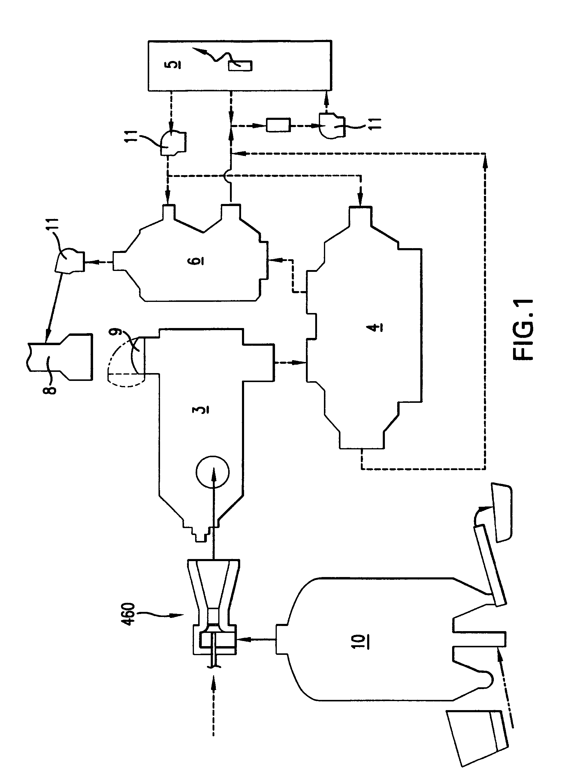
[0061]Referring now to the figures, the pyrolyzing gasification system and its method of use will now be described in detail. A schematic illustration of the system, shown in FIG. 1, includes an all-refractory gasifier 10, an all-refractory, staged cyclonic oxidizer 3, and an all-refractory air-to-air indirect heat exchanger 4. The inventive system for recycling biomass waste into useful ash and recoverable heat energy without formation of toxic by-product gases provides partial primary combustion of biomass, or other solid fuel, within pyrolyzing gasifier 10. This combustion occurs at low substoichiometric air percentages of 10–30 percent and at temperatures below 1000 degrees F., forming a useable ash and a primary combustion flue gas. Following gasification, secondary combustion of the primary combustion flue gas is performed within a staged, cyclonic oxidizer 3, forming a generally clean oxidized flue gas. Following oxidation, heat energy is recovered from the oxidized flue gas ...


PUM

PropertyMeasurementUnit
ashaaaaaaaaaa
ashaaaaaaaaaa
ashaaaaaaaaaa

Abstract

The gasifier includes a furnace bed segmented into individual cells, each cell is independently monitored using a ramp temperature probe, and provided with controlled air injection to provide individually controlled burn regions within the gasifier. Gasifier air injection includes tuyere arrays, lances, or both.

Description

BACKGROUND OF THE INVENTION[0001]Gasification of biomass or other solid fuel is a process whereby air or oxygen is limited in the gasification chamber to achieve thermal degradation of complex materials with only partial combustion of the fuel. This limited air process is referred to as starved air, substoichiometric air, or pyrolysis. The latter, scientifically defined as the thermal degradation of complex material in an inert atmosphere or a vacuum is used herein and conventionally understood in the art to mean starved air or substoichiometric air. The resultant gases from this thermal degradation or gasification are subsequently oxidized in a second unit operation utilizing staged oxidation or staged introduction of air to complete or nearly complete the oxidation, or burn off, process. In application, this gasification and oxidation of fuel often includes a third step in which thermal energy is recovered from the flue gas using a heat recovery device such as a steam boiler or ai...

Claims


Application Information

Patent Timeline
Patent Type & Authority Patents(United States)
IPC IPC(8): C10J3/00F23B30/00F23G5/027F23G5/24F23G5/46F23G5/50
CPCC10J3/20C10J3/30C10J3/34C10J3/723F23G5/027F23G5/24F23G5/46F23G5/50C10J2200/09C10J2200/158C10J2300/0916C10J2300/092C10J2300/093C10J2300/0946C10J2300/0956C10J2300/1687C10J2300/1876F23G2201/303F23G2206/10F23G2206/202F23G2207/101Y02E20/12Y02E50/12Y02E50/14Y02E50/10Y02P20/10Y02P20/129
Inventor GRAHAM, ROBERT G.
Owner HEAT TRANSFER INT
Why Eureka
Try Eureka