Solar cell electrolysis of water to make hydrogen and oxygen

a solar cell and electrolysis technology, applied in electrochemical generators, batteries, pv power plants, etc., can solve the problems of low efficiency, high overpotential of photoelectrodes, and limited system life, so as to improve durability, reduce semiconductor corrosion during the operation of the apparatus, and avoid energy loss. incurred

Inactive Publication Date: 2007-07-10
GAS TECH INST
View PDF5 Cites 19 Cited by
  • Summary
  • Abstract
  • Description
  • Claims
  • Application Information

AI Technical Summary

Benefits of technology

[0008]It is, thus, one object of this invention to provide an apparatus for direct splitting of water to produce hydrogen having improved efficiency over conventional photoelectrolytic systems for hydrogen generation.
[0009]It is another object of this invention to provide an apparatus for direct splitting of water to produce hydrogen having improved durability over conventional photoelectrolytic systems for hydrogen generation.
[0010]It is yet a further object of this invention to provide an apparatus for direct splitting of water to produce hydrogen in which semiconductor corrosion during operation of the apparatus is reduced compared to conventional photoelectrolytic systems for hydrogen generation.

Problems solved by technology

These low efficiencies are in part due to efficiency losses from sunlight absorption by a liquid electrolyte layer, impediments to the departure of product gases from the photoelectrodes due to electrolyte surface tension, and high overpotential of the photoelectrodes.
In addition, system life is limited by photocorrosion and electrochemical corrosion of the electrode.
Further, the costs of all these devices are too high for wide use.
The current design of photoelectrodes is an additional hindrance to the development of improved photoelectrochemical systems because the semiconductors employed therein are fabricated on conductive substrates.
With this type of design, there is no way to reduce the thickness of the electrolyte layer and eliminate the surface tension that acts as an inhibitor to the release of product gases because the reactant water and electrolyte must be transported to the front of the electrode.

Method used


Image

  • Solar cell electrolysis of water to make hydrogen and oxygen
  • Solar cell electrolysis of water to make hydrogen and oxygen
  • Solar cell electrolysis of water to make hydrogen and oxygen

Examples


Embodiment Construction

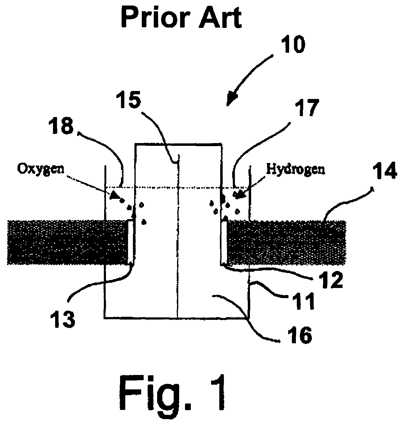
[0022]FIG. 1 is a diagram showing a conventional water-splitting photoelectrochemical cell 10, which cell comprises a transparent housing or enclosure 11 filled with an electrolyte (e.g. water and H2SO4) 16, a semiconductor photoanode 13 and a semiconductor photocathode 12, both of which comprise a light sensitive catalytic material, disposed within and surrounded by the electrolyte and a separator 15 also disposed within the electrolyte separating the semiconductor photoanode 13 from the semiconductor photocathode 12. The hydrogen half-cell reaction for this cell is:

2H+ (aq)+2e−→H2 (g) O V vs. NHE

and the oxygen half-cell reaction is:

2H2O (l)+4h+→4H+ (aq)+O2 (g) 1.23 V vs. NHE

Thus, the total reaction is:

2H2O→2H2 (g)+O2 (g)

Therefore, in the whole reaction, there is no loss of a proton.

[0023]As can be seen in FIG. 1, conventional photoelectrochemical cells, also sometimes referred to herein as photoelectrolysis cells, have a thick layer 17, 18 of liquid electrolyte (e.g. a water / acid ...


PUM

PropertyMeasurementUnit
voltageaaaaaaaaaa
n-type semiconductoraaaaaaaaaa
band gapaaaaaaaaaa

Abstract

A water permeable electrode for electrochemical splitting of water having a light sensitive catalytic material layer which includes a light sensitive catalytic material and a semiconductor, a polymer electrolyte membrane layer, a metallic substrate layer disposed there between adjacent the polymer electrolyte membrane layer, and at least one photovoltaic device connected in series to the light sensitive catalytic material layer and disposed between the light sensitive catalytic material layer and the metallic substrate layer.

Description

BACKGROUND OF THE INVENTION[0001]1. Field of the Invention[0002]This invention relates to an apparatus for producing hydrogen directly from solar energy. More particularly, this invention relates to direct photoelectrolysis of water to generate hydrogen directly with sunlight employing a combination of advances in fuel cell technology, photovoltaic technology, photoelectrochemistry, and thin film technology.[0003]2. Description of Related Art[0004]Solar hydrogen generation represents an important long-term objective for the energy industry. Hydrogen is an important future energy carrier and energy storage medium. Efficient, low-cost methods of making hydrogen from renewable solar energy are an important element of the future hydrogen economy. With clean and abundant solar energy, solar photovoltaic, photoelectrochemical, or photocatalytic hydrogen generation could become viable technologies. However, to make this a reality, it is necessary to reduce costs, increase efficiency, and i...

Claims


Application Information

Patent Timeline
Patent Type & Authority Patents(United States)
IPC IPC(8): H01L31/048H01L31/00H01M6/30
CPCH01L31/076C25B1/003Y10S136/291Y02E60/368Y02E10/548C25B1/55Y02E60/36
Inventor FAN, QINBAIONISCHAK, MICHAELLISS, WILLIAM E.
Owner GAS TECH INST
Why Eureka
Try Eureka