Composite dielectric, composite dielectric sheet, composite dielectric paste, metal-layered composite dielectric, wiring board and multilayer wiring board

a dielectric and composite technology, applied in the direction of metal layered products, natural mineral layered products, metal layered products, etc., can solve the problems of electronic components that may disadvantageously generate heat, substrate materials that do not meet all, and the transmission loss tends to increase, etc., to achieve excellent dielectric characteristics, excellent dielectric characteristics, and high dielectric constant

Inactive Publication Date: 2007-07-24
TDK CORPARATION
View PDF16 Cites 22 Cited by
  • Summary
  • Abstract
  • Description
  • Claims
  • Application Information

AI Technical Summary

Benefits of technology

[0015]In view of the foregoing circumstances, it is an object of the present invention to provide a composite dielectric and a composite dielectric sheet which exhibit not only excellent dielectric characteristics in a high frequency region but also high heat resistance and low water absorption, and can easily form a thin wiring board. It is another object of the present invention to provide a metal-layered composite dielectric sheet, a composite dielectric paste, a wiring board, and a multilayer wiring board which comprise such a composite dielectric sheet.
[0030]Since the composite dielectric of the present invention has a high dielectric constant and a high Q value, the composite dielectric sheet constituted by the composite dielectric, the wiring board and multilayer wiring board comprising the same have an excellent dielectric characteristic of a high dielectric constant with a low dielectric dissipation factor, thereby yielding a very low transmission loss even in a high frequency region (region of 1 to 5 GHz in particular). Also, the aromatic liquid crystal polyester constituting the composite dielectric has an excellent heat resistance and a low water absorption, so that the resulting wiring board and multilayer wiring board exhibit a high heat resistance and a very small change in dielectric characteristics. Therefore, the wiring board and multilayer wiring board obtained by use of the composite dielectric dispersion of the present invention can favorably be used as a wiring board applicable to high frequencies.

Problems solved by technology

As the frequency of transmitted signals increases, however, transmission loss tends to increase in the process of transmission, whereby electronic components may disadvantageously generate heat because of the thermal energy caused by the transmission loss, and so forth.
However, these substrate materials do not satisfy all of the above-mentioned characteristics, and are often insufficient in terms of both characteristics of high heat resistance and low water absorption.
However, in case of these molding methods, it is hard to yield a thin sheet, and the resulting sheet often exhibits anisotropy.
Though a method which erases the anisotropy by applying a force in a direction perpendicular to the sheet extruding direction has been under consideration, sheets made of aromatic liquid crystal polyesters tend to exhibit a low dielectric constant in any case, and their dielectric characteristics are insufficient for use as a substrate material.

Method used

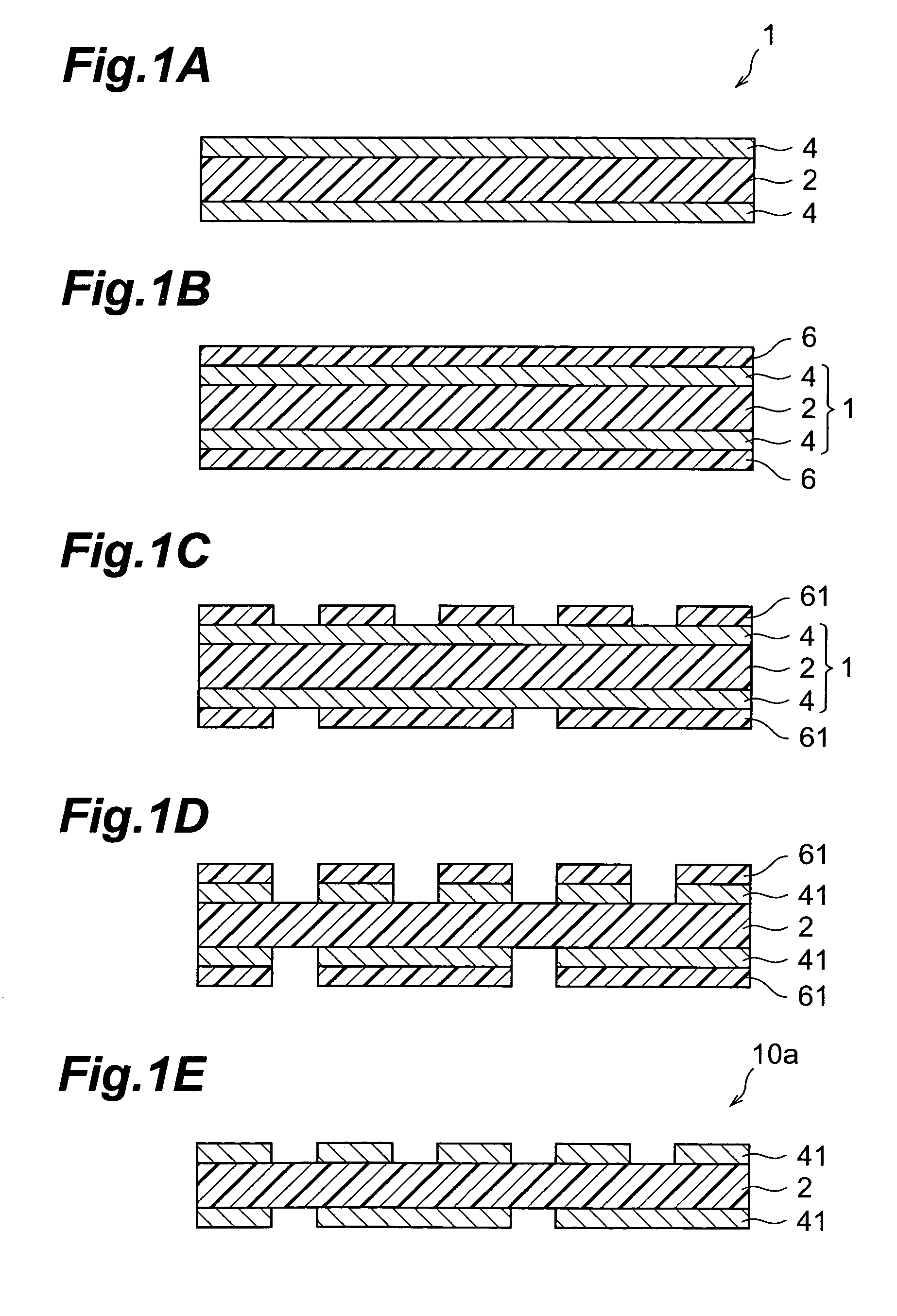
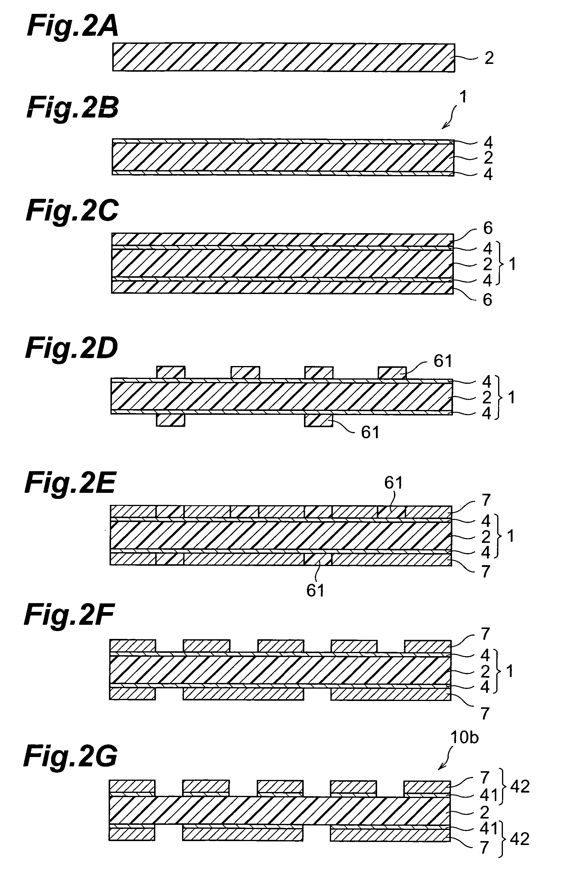
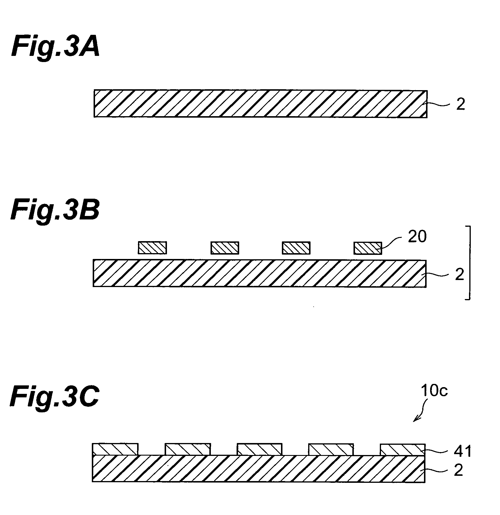

Image

  • Composite dielectric, composite dielectric sheet, composite dielectric paste, metal-layered composite dielectric, wiring board and multilayer wiring board
  • Composite dielectric, composite dielectric sheet, composite dielectric paste, metal-layered composite dielectric, wiring board and multilayer wiring board
  • Composite dielectric, composite dielectric sheet, composite dielectric paste, metal-layered composite dielectric, wiring board and multilayer wiring board

Examples


synthesis example 1

[0094]Into a reactor equipped with a stirrer, a torque meter, a nitrogen gas feeding tube, a thermometer and a reflux condenser, 191.8 g (1.02 mol) of 2-hydroxy-6-naphthoic acid, 63.3 g (0.34 mol) of 4,4′-dihydroxybiphenyl, 56.5 g (0.34 mol) of isophthalic acid and 191 g (1.87 mol) of acetic anhydride were introduced. The inside of the reactor was sufficiently substituted by nitrogen gas, and the temperature therein was raised to 150° C. over 15 minutes under a nitrogen gas flow. Then, while the temperature was held at 150° C., reflux was carried out for 3 hours.

[0095]After the reflux, while evaporating acetic acid, which was a flowing-out byproduct, and the unreacted part of acetic anhydride, the temperature was raised to 320° C. over 170 minutes. A point where an increase in torque was seen was considered to be the end point of reaction, and the content of the reactor in this state was taken out. Thus obtained solid was cooled to room temperature and then was pulverized. The pulve...

synthesis example 2

[0096]Into a reactor equipped with a stirrer, a torque meter, a nitrogen gas feeding tube, a thermometer and a reflux condenser, 191.8 g (1.02 mol) of 2-hydroxy-6-naphthoic acid, 63.3 g (0.34 mol) of 4,4′-dihydroxybiphenyl, 56.5 g (0.34 mol) of isophthalic acid and 191 g (1.87 mol) of acetic anhydride were introduced. The inside of the reactor was sufficiently substituted by nitrogen gas, and the temperature therein was raised to 150° C. over 15 minutes under a nitrogen gas flow. Then, while the temperature was held at 150° C., reflux was carried out for 3 hours.

[0097]After the reflux, while evaporating acetic acid, which was a flowing-out byproduct, and the unreacted part of acetic anhydride, the temperature was raised to 320° C. over 170 minutes. A point where an increase in torque was seen was considered to be the end point of reaction, and the content of the reactor in this state was taken out. Thus obtained solid was cooled to room temperature and then was pulverized. The pulve...

example 1

[0098]While being stirred at 120° C., 5 g of the aromatic liquid crystal polyester obtained in Synthesis Example 2 were added to 95 g of p-chlorophenol, and were completely dissolved therein. As a dielectric ceramic powder, 2.3 g of BaNd2Ti4O12 (manufactured by TDK Corporation, with an average particle diameter of 1.6 μm and ∈92 / Q1700) were added to the solution, and mixed / dispersed therein, so as to yield a composite dielectric paste.


PUM

PropertyMeasurementUnit
frequencyaaaaaaaaaa
mol %aaaaaaaaaa
mol %aaaaaaaaaa

Abstract

The composite dielectric of the present invention contains an aromatic liquid crystal polyester and a dielectric ceramic powder arranged in the aromatic liquid crystal polyester, wherein the dielectric ceramic powder exhibits a Q value greater than 650 at a frequency of 1 GHz by perturbation. A wiring board comprising a composite dielectric sheet made of a composite dielectric having such a characteristic exhibits a high dielectric constant and a low dielectric dissipation factor, thereby yielding less transmission loss, and thus can favorably be used in electronic instruments driven in high-frequency regions.

Description

BACKGROUND OF THE INVENTION[0001]1. Field of the Invention[0002]The present invention relates to a composite dielectric, a composite dielectric sheet, a composite dielectric paste, a metal-layered composite dielectric sheet, a wiring board and a multilayer wiring board.[0003]2. Related Background of the Invention[0004]Recently, as information transmitted through electronic devices such as information and communication devices increases, wiring boards and the like mounted to these electronic devices have been required to be applicable to higher frequencies of GHz bands. As the frequency of transmitted signals increases, however, transmission loss tends to increase in the process of transmission, whereby electronic components may disadvantageously generate heat because of the thermal energy caused by the transmission loss, and so forth. In general, such a transmission loss is represented by the following expression:(transmission loss)=(coefficient)×(frequency)×(dielectric constant)1 / 2...

Claims


Application Information

Patent Timeline
Patent Type & Authority Patents(United States)
IPC IPC(8): C04B35/01B32B15/09B32B18/00C09K19/52H05K1/03C08L67/03C04B35/468C04B35/50C08G63/60C08K3/22C09K19/02C09K19/38G03C1/85H05K3/20H05K3/46
CPCC04B35/468C04B35/50C09K19/02C09K19/3809H05K1/0373H05K3/4626Y10T428/24917H05K2201/0145H05K2201/0209C04B2235/3213C04B2235/3215C04B2235/3224C04B2235/3284C04B2235/5436C08G63/605H05K3/20Y10T428/24926Y10T428/1095Y10T428/252H05K2201/0141C09K2323/061
Inventor KAWABATA, KENICHIMORITA, TAKAAKI
Owner TDK CORPARATION
Why Eureka
Try Eureka