Adaptive controller for linearization of transmitter

a linearization controller and transmitter technology, applied in the field of transmitters, can solve the problems of large hardware resources needed for the implementation of precision trigonometric/inverse trigonometric, the complexity of predistorter gain should be added to the respective algorithms, and the limited relevance of contemporary wideband communication standards, so as to reduce the susceptibility to signal changes

Active Publication Date: 2007-07-31
APPLE INC
View PDF10 Cites 25 Cited by
  • Summary
  • Abstract
  • Description
  • Claims
  • Application Information

AI Technical Summary

Benefits of technology

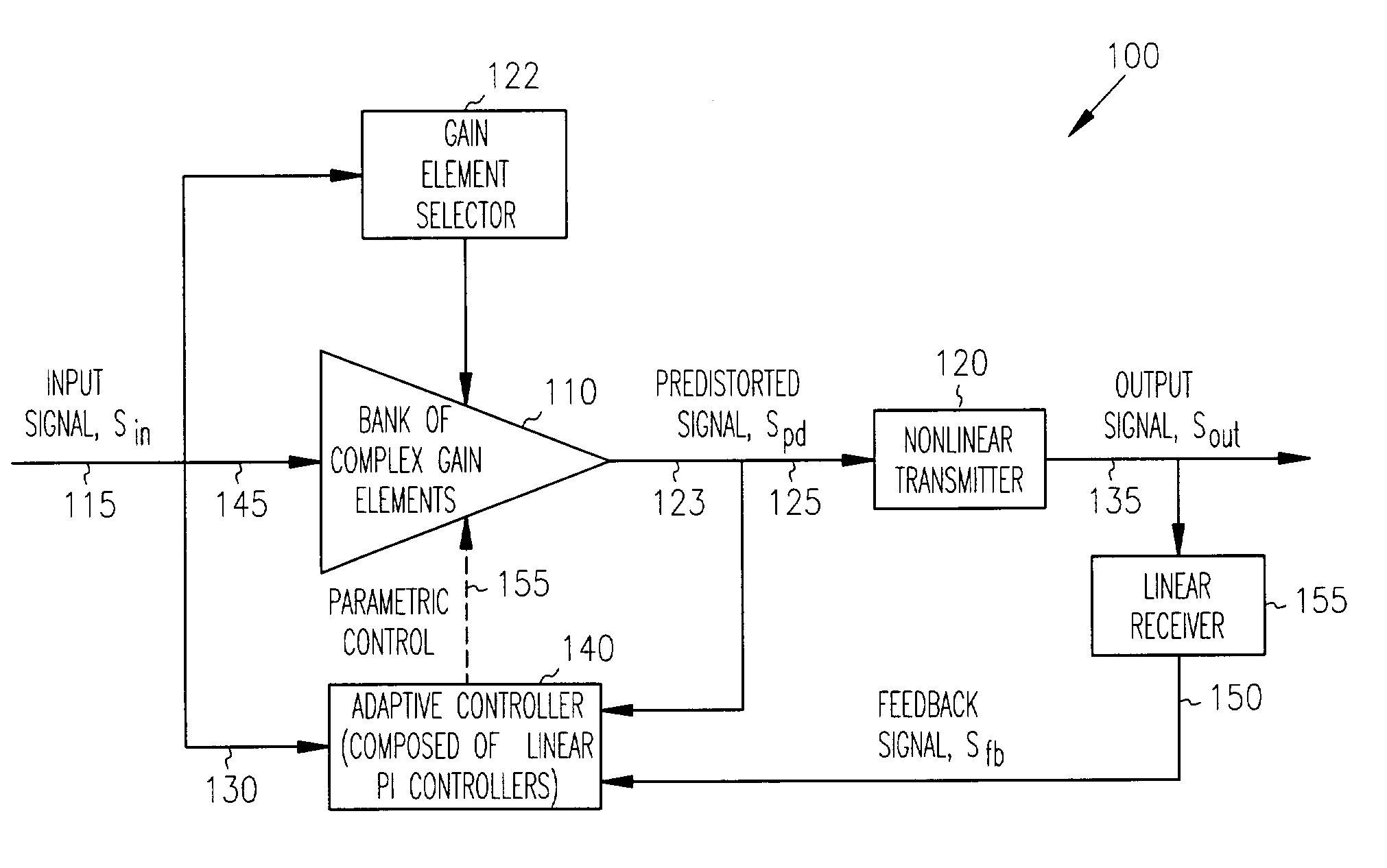
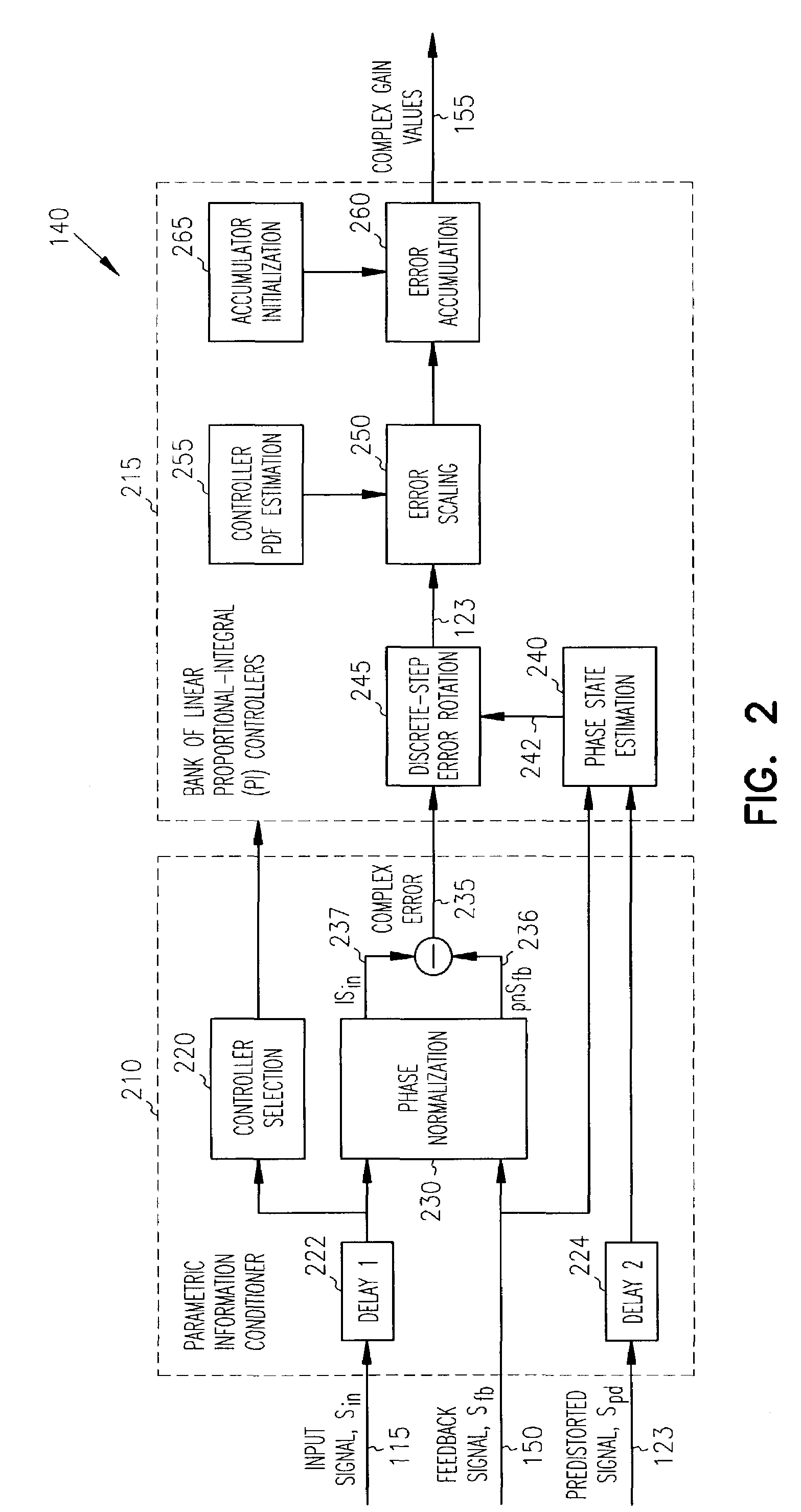
[0016]In one embodiment, the error difference cancellation is accomplished by a bank of linear adaptive controllers through three stages of processing including (1) error phase normalization, (2) error magnitude normalization, and (3) error scaling and integration, which provide respectively unconditional stability (stage 1), lowered susceptibility to signal changes (stage 2) and low-pass noise filtering of the adaptation process (stage 3).
[0017]In a fu

Problems solved by technology

Despite a big diversity of existing approaches aimed at improving the quality of RF power amplification, many of the older solutions are constrained to usage with specific discrete-level signaling formats, and, thus have a limited relevance to contemporary wideband communication standards.
On the other hand, from the perspective of real-time adaptation of the predistorter gain more complexity should be added to the respective algorithms because of the nonlinear behavior of the predistortion gain gradient as a function of the average phase of the linearized transmitter gain.
On the other hand, the biggest disadvantages are the large amount of hardware resources needed for the implementation of precision trigonometric/inverse-trigonometric functions performing the coordinate transformations and, most importantly, the noise-biasing effects associated with processing the modulus of noisy complex data.
However, the error

Method used


Image

  • Adaptive controller for linearization of transmitter
  • Adaptive controller for linearization of transmitter
  • Adaptive controller for linearization of transmitter

Examples


Embodiment Construction

[0022]In the following description, reference is made to the accompanying drawings that form a part hereof, and in which is shown by way of illustration specific embodiments in which the invention may be practiced. These embodiments are described in sufficient detail to enable those skilled in the art to practice the invention, and it is to be understood that other embodiments may be utilized and that structural, logical and electrical changes may be made without departing from the scope of the present invention. The following description is, therefore, not to be taken in a limited sense, and the scope of the present invention is defined by the appended claims.

[0023]References to signals and lines carrying such signals are made with the same reference number. While the invention is described with respect to circuitry, and blocks representing such circuitry, it is recognized that various combinations of software, hardware and firmware may be used provided adequate processing speed is...


PUM


Abstract

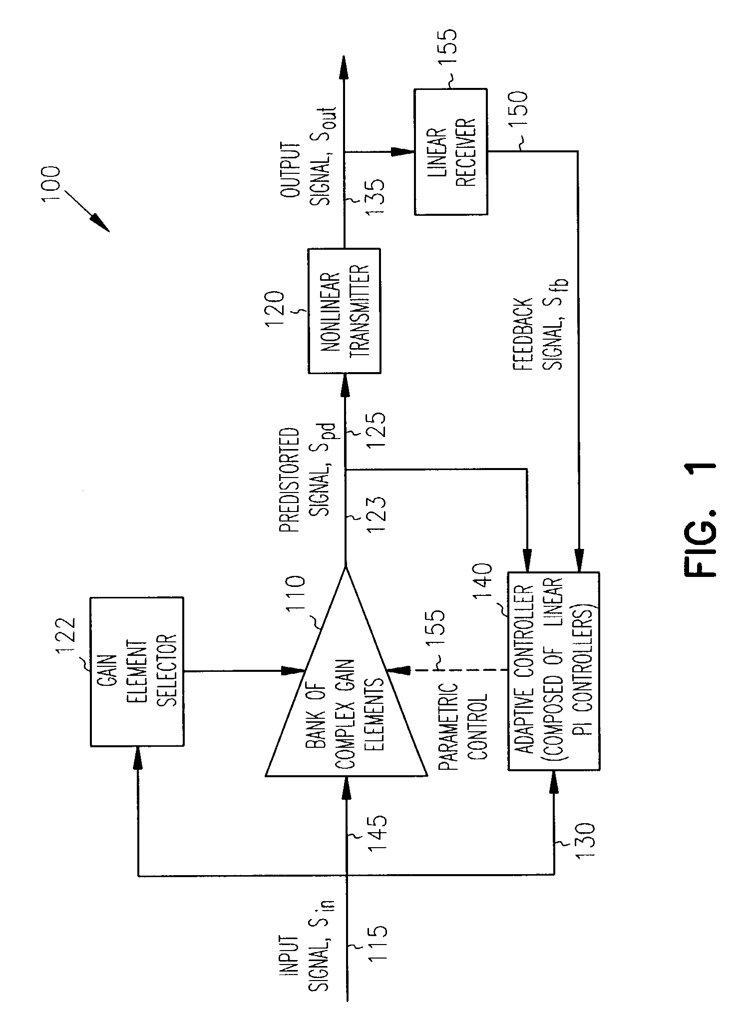
A bank of complex gain elements is used to provide a step-wise approximation of an arbitrary complex-gain predistortion function for a nonlinear transmitter. The bank of gain elements is in an adaptive loop realizing adaptive control. The adaptive loop is closed between an Input of the gain bank and an output of the transmitter through a linear receiver at an adaptive controller composed of a bank of proportional-integral (PI) controllers. The real and imaginary parts of each predistortion gain element are controlled by a corresponding adaptive PI controller. The signals processed by the adaptive controller are represented in orthogonal coordinates in terms of real and imaginary number pairs of complex numbers. The adaptive controller achieves unconditionally stable operation independently from the arbitrary phase rotation in the input signal or the adaptive loop.

Description

Incorporation by Reference[0001]Co-pending commonly assigned U.S. patent application Ser. No. 10 / 321,045 filed on the same date herewith and titled “Adaptive Controller for Linearization of Transmitter with Impairments” is hereby incorporated by reference.FIELD OF THE INVENTION[0002]The present invention relates to transmitters, and in particular to an adaptive linearization controller for a transmitter.BACKGROUND OF THE INVENTION[0003]Some signal transmitters for cellular communications utilize QAM (quadrature amplitude modulation) to increase the number of signals that can be transmitted on a given channel. QAM is a method of combining two amplitude-modulated (AM) signals into a single channel to effectively double the effective bandwidth. QAM is used with pulse amplitude modulation (PAM) in digital systems, especially in wireless applications.[0004]In a QAM (quadrature amplitude modulation) signal, there are two carriers, each having the same frequency but differing in phase by 9...

Claims


Application Information

Patent Timeline
IPC IPC(8): H04K1/02H03F1/02H03F1/32H03F3/72
CPCH03F1/0277H03F1/3247H03F3/72H03F2203/7215H03F2203/7236
Inventor RASHEV, PETER ZAHARIEVTHOLL, DAVID M.LESKIW, CHRISTOPHER JOHN
Owner APPLE INC
Why Eureka
Try Eureka