Method for producing nano-carbon materials

a technology of carbon materials and nano-carbon materials, applied in the direction of bulk chemical production, supercritical condition processes, chemical processes, etc., can solve the problems of unavoidably expensive products, difficult quantitatively producing nano-carbon materials, and unavoidably expensive products obtained by any of these methods

Inactive Publication Date: 2007-09-18
CANON KK
View PDF26 Cites 49 Cited by
  • Summary
  • Abstract
  • Description
  • Claims
  • Application Information

AI Technical Summary

Benefits of technology

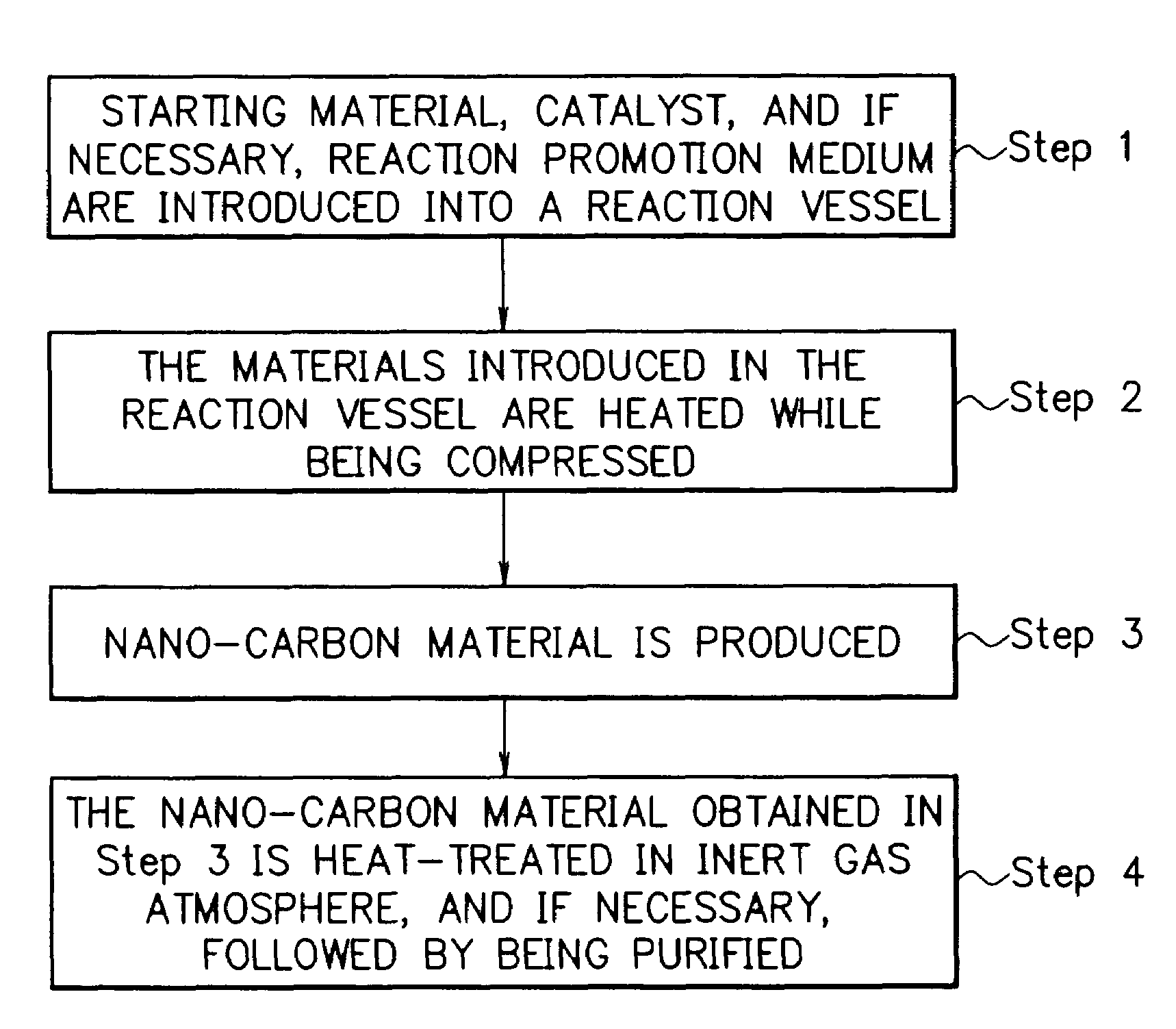
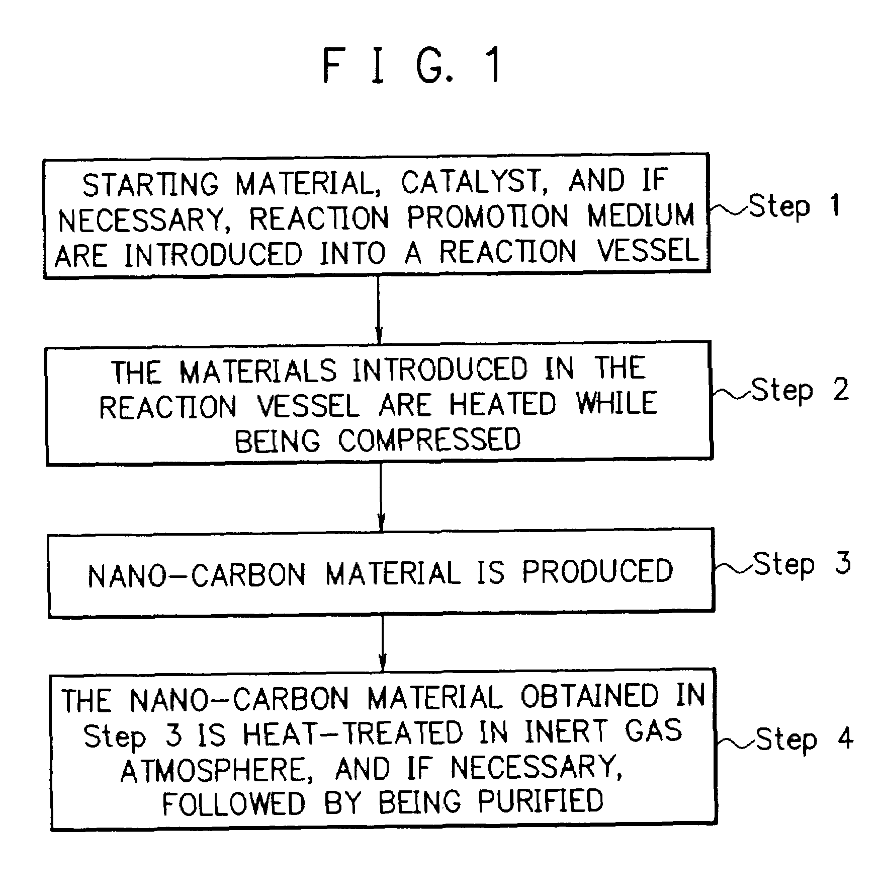
[0021]The present invention makes it an object to provide a method, which enables one to efficiently and quantitatively produce high quality nano-carbon materials, which are effectively usable as electrode materials in FEDs (field emission displays), as electrode materials in rechargeable lithium batteries, and as catalyst-retaining materials in fuel cells, at a reasonable production cost from relatively inexpensive raw material in a simple manner.
[0038]The first embodiment and the second embodiment in the present invention preferably include a purification step in which the heat-treated product is purified. Specifically, in the case where the nano-carbon materials contained in the heat-treated reaction product contain a magnetic metal element obtained from the catalyst, the magnetic metal element-containing nano-carbon materials are collected by a magnet, whereby it is possible to obtain a purified nano-carbon materials-containing product. Separately, in the case where the nano-carbon materials contain a transition metal or a transition metal compound obtained from the catalyst and it is not necessary for the nano-carbon materials to contain such a transition metal or such transition metal compound, it is possible to remove such transition metal or such transition metal compound by washing with an acid or the like.

Problems solved by technology

However, the methods disclosed in patent Documents 1 to 5 have disadvantages such that the starting material and the apparatus used for practicing the method are costly and therefore a product obtained becomes unavoidably costly and it is difficult to quantitatively produce nano-carbon materials.
Similarly, the methods described in Non-patent Documents 1 to 3 have disadvantages in that because high pressure of 100 MPa is used, a specific high pressure capsule made of Au (which is costly) and which can withstand such high pressure is employed as the reaction vessel, and the starting material and water are introduced into the capsule, wherein the starting material is subjected to a hydrothermal reaction at a high temperature (700 to 800° C.) under a high 100 MPa pressure.
Therefore, a product obtained by any of these methods unavoidably becomes costly.
Although this method is advantageous in that the reaction pressure upon forming a nano-carbon material (a carbon nanotube having a multi-layered structure) is low (about 15 Pa), the method has a disadvantage in that the amount of a nano-carbon material produced in the reaction after a relatively long time (12 hours) is small.
This means that the nano-carbon material obtained by the method described in Non-patent Document 4 is accompanied by a number of lattice defects.

Method used


Image

  • Method for producing nano-carbon materials
  • Method for producing nano-carbon materials
  • Method for producing nano-carbon materials

Examples


example 1

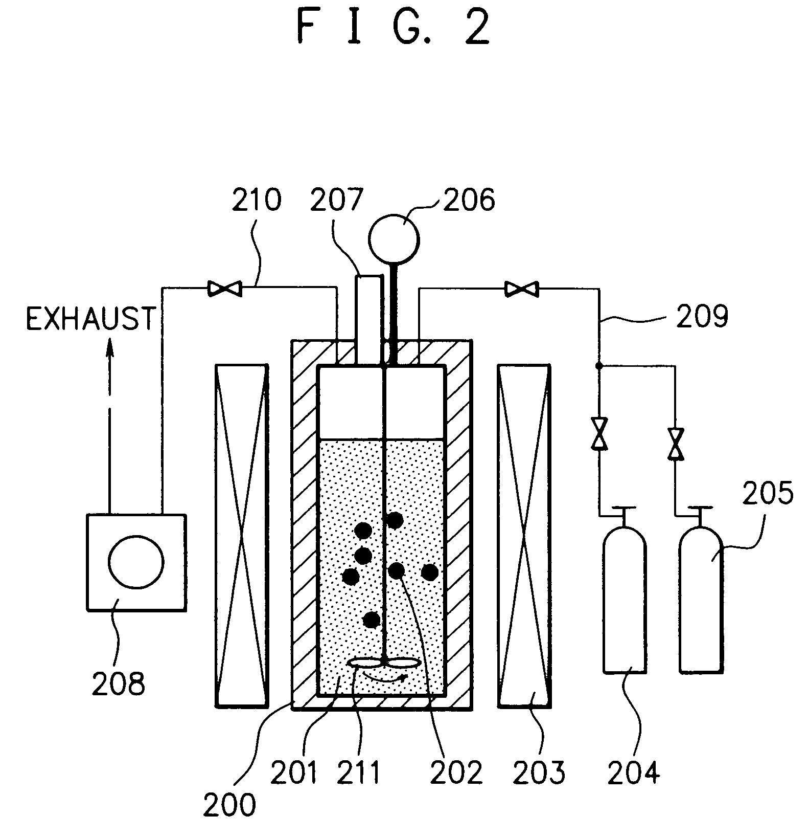
[0192]After the pressure reaction vessel made of a Hastelloy (trademark name: comprising a Ni—Mo alloy, produced by Haynes International Inc.) with an inner volume of 95 ml of the reaction apparatus shown in FIG. 2 was evacuated to a prescribed vacuum by the vacuum pump, 2.5 g of n-hexane (the critical temperature: 234.4° C.; the critical pressure: 2.97 MPa) as the starting material and 0.2 g of a nickelocene (bis(cyclopentadienyl)nickel) as the catalyst were introduced into the reaction vessel, followed by adding thereto 30g of dry ice as the reaction promotion medium. The reaction vessel was closed, where the dry ice evaporated to form CO2 gas at room temperature. Therefore, a part of said CO2 gas was exhausted outside the reaction vessel to adjust the inner pressure of the reaction vessel to a desired value. The materials in the reaction vessel were subjected to a reaction at a temperature of 650° C. while being compressed at a pressure of 23 MPa and while being agitated by the a...

example 2

[0211]In this example, there were provided two substantially enclosed pressure reaction vessels made of a Hastelloy (trademark name: comprising a Ni—Mo alloy, produced by Haynes International Inc.) with an inner volume of 95 ml as the pressure reaction vessel (200) of the reaction apparatus shown in FIG. 2. Separately using these two reaction vessels, the procedures of Example 1 for the production of the nano-carbon product (a) were repeated, except that the reaction temperature and the reaction pressure were changed to 450° C. and 14 MPa, respectively, and the reaction time was changed to 6 hours, to separately obtain a powdery nano-carbon product (i) in an amount of 0.40 g in one reaction vessel and a powdery nano-carbon product (ii) in an amount of 0.82 g in another reaction vessel. In this case, the oxygen content and the moisture content in the two reaction vessels were not precisely controlled so as to be substantially the same upon introducing the starting material, the catal...

example 3

[0214]The procedures of Example 1 for the production of the nano-carbon product (a) were repeated, except that the reaction temperature was changed to 450° C., the reaction time was changed to 6 hours, the reaction pressure was changed to a prescribed pressure value in a range of from 14 to 16 MPa (see, Table 1). Also, instead of the nickelocene as the catalyst, a nickel fine powder, a cobalt fine powder, a nickel-retained silica powder, a nickel-retained alumina powder, a nickel-retained alumina powder, a palladium-retained alumina powder, and a nickel oxide powder were separately used, to obtain a powdery nano-carbon product for each of these catalysts.

[0215]The results of the SEM observation revealed that each of the nano-carbon products contained a substantially large number of filament-like shaped nano-carbon microunits, which were gathered.

[0216]The reaction pressure, the yield of the nano-carbon product, the amount of the catalyst used, and the diameter of the microunits in t...


PUM

PropertyMeasurementUnit
pressureaaaaaaaaaa
temperatureaaaaaaaaaa
pressureaaaaaaaaaa

Abstract

A method for producing nano-carbon materials, having a step wherein a starting material comprising one or more kinds of compounds selected from the group consisting saturated hydrocarbons, unsaturated hydrocarbons, saturated cyclic hydrocarbons, and alcohols whose atomic ratio of the component carbon to the component oxygen is more than 2.0 and a catalyst are together treated at a temperature in a range of from 100 to 800° C. while being compressed at a pressure in a range of from 0.2 to 60 MPa.

Description

BACKGROUND OF THE INVENTION[0001]1. Field of the Invention[0002]The present invention relates to a method for producing nano-carbon materials. More particularly, the present invention relates to a method, which enables one to quantitatively produce nano-carbon materials from a relatively inexpensive starting material in a simple manner using a relatively inexpensive reaction apparatus. The nano-carbon materials produced according to the present invention include carbon nanotubes, carbon nanofibers, and the like.[0003]2. Related Background Art[0004]A fullerene C60 having a soccer ball-like polyhedral molecular structure comprising 60 carbon atoms was discovered by H. W. Kroto, R. E. Smallry and R. F. Curl in 1985. Following the discovery of the fullerene C60, a carbon nanotube (CNT) corresponding to a cylindrical molecule of a fullerene, specifically having a molecular structure in which a graphene sheet (a single atomic layer of crystalline graphite) rolled up into a cylinder, was d...

Claims


Application Information

Patent Timeline
Patent Type & Authority Patents(United States)
IPC IPC(8): D01F9/12B01J3/00B82B3/00C01B31/02
CPCB01J3/006B01J3/008B82Y30/00B82Y40/00C01B31/0233B01J2219/00063B01J2219/00065B01J2219/00162B01J2219/00164C01B2202/06Y10S977/842C01B32/162Y02P20/54B82B3/00
Inventor KAWAKAMI, SOICHIROINOUE, KATSUHIKOSANO, HITOMISUZUKI, NOBUYUKI
Owner CANON KK
Why Eureka
Try Eureka