

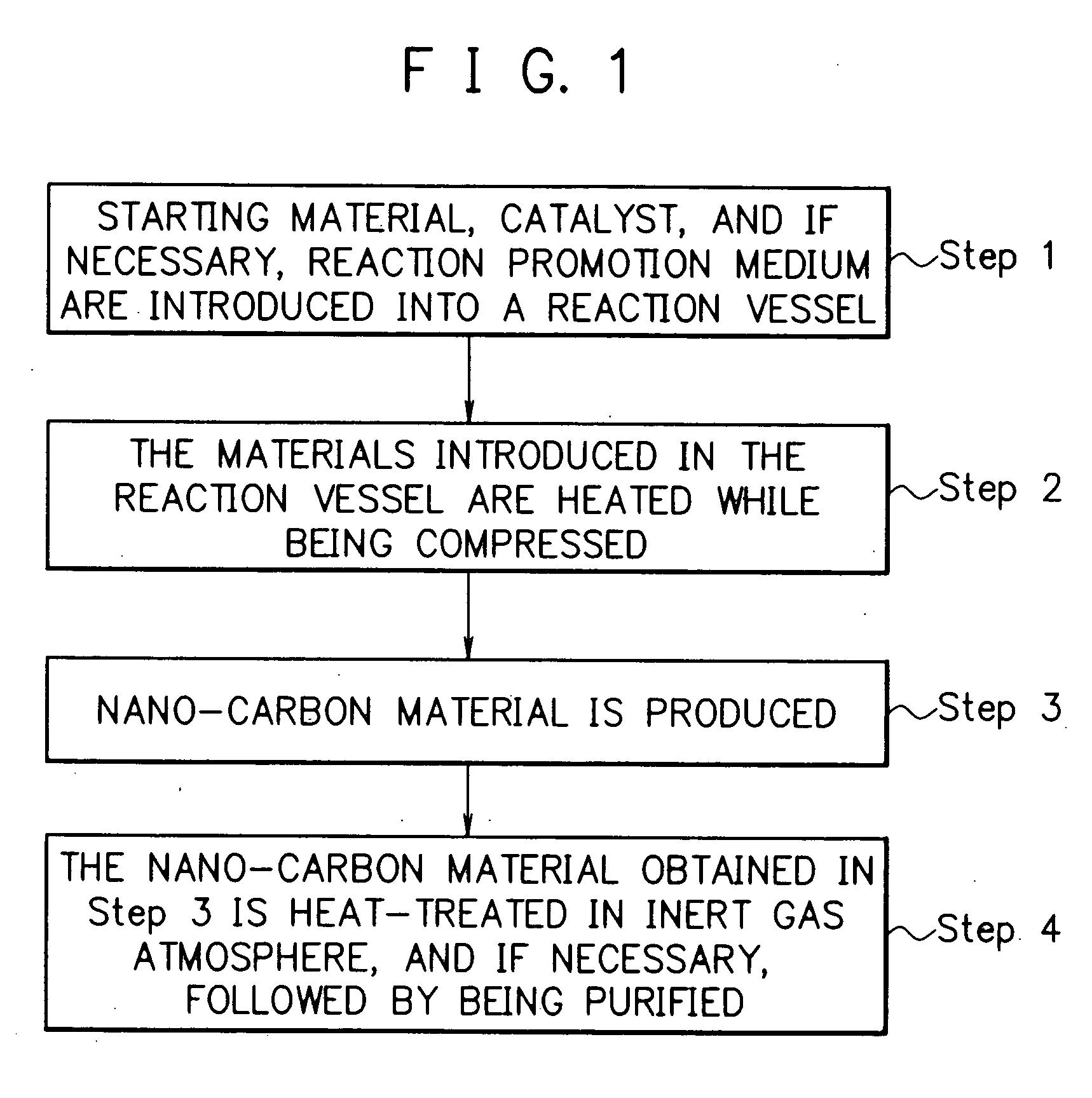
Method for producing nano-carbon materials
a technology of carbon materials and nano-carbon materials, applied in the direction of bulk chemical production, supercritical condition processes, pressurized chemical processes, etc., can solve the problems of unavoidably expensive products, difficult quantitatively producing nano-carbon materials, and unavoidably expensive products obtained in any of these methods
- Summary
- Abstract
- Description
- Claims
- Application Information
AI Technical Summary
Benefits of technology
Problems solved by technology
Method used
Image

Examples
example 1
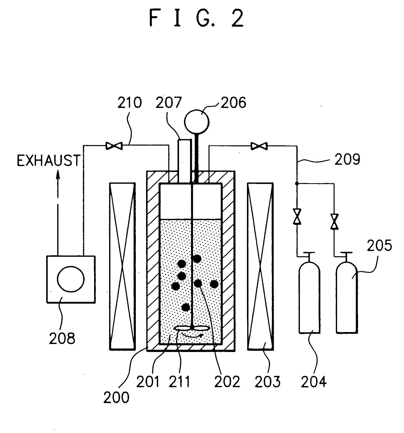
[0193] After the pressure reaction vessel made of a Hastelloy (trademark name: comprising a Ni—Mo alloy, produced by Haynes International Inc.) with an inner volume of 95 ml of the reaction apparatus shown in FIG. 2 was evacuated to a prescribed vacuum by means of the vacuum pump, 2.5 g of n-hexane (the critical temperature: 234.4° C.; the critical pressure: 2.97 MPa) as the starting material and 0.2 g of a nickelocene (bis(cyclopentadienyl)nickel) as the catalyst were introduced into the reaction vessel, followed by adding 30 g of dry ice as the reaction promotion medium thereto, and the reaction vessel was closed, where said dryice was vaporized into CO2 gas at room temperature and therefore, part of said CO2 gas was exhausted outside the reaction vessel to adjust the inner pressure of the reaction vessel to a desired value. And the materials in the reaction vessel were subjected to reaction at a temperature of 650° C. while being compressed at a pressure of 23 MPa and while agita...
example 2
[0212] In this example, there were provided two substantially enclosed pressure reaction vessels made of a Hastelloy (trademark name: comprising a Ni—Mo alloy, produced by Haynes International Inc.) with an inner volume of 95 ml as the pressure reaction vessel (200) of the reaction apparatus shown in FIG. 2. Separately using these two reaction vessels, the procedures of Example 1 for the production of the nano-carbon product (a) were repeated, except that the reaction temperature and the reaction pressure were changed to 450° C. and 14 MPa respectively, and the reaction time was changed to 6 hours, to separately obtain a powdery nano-carbon product (i) in an amount of 0.40 g in one reaction vessel and a powdery nano-carbon product (ii) in an amount of 0.82 g in another reaction vessel. In this case, the oxygen content and the moisture content in the two reaction vessels were not precisely controlled so as to be substantially the same upon introducing the starting material, the catal...
example 3
[0215] The procedures of Example 1 for the production of the nano-carbon product (a) were repeated, except that the reaction temperature was changed to 450° C., the reaction time was changed to 6 hours, the reaction pressure was changed to a prescribed pressure value in a range of from 14 to 16 MPa (see, Table 1), and instead of the nickelocene as the catalyst, a nickel fine powder, a cobalt fine powder, a nickel-retained silica powder, a nickel-retained alumina powder, a nickel-retained alumina powder, a palladium-retained alumina powder, and a nickel oxide powder were separately used, to obtain a powdery nano-carbon product for each of these catalysts.
[0216] The results of the SEM observation revealed that any of the nano-carbon products contains an enormous number of filament-like shaped nano-carbon microunits which are gathered.
[0217] The reaction pressure, the yield of the nano-carbon product, the use amount of the catalyst, and the diameter of the microunits in the nano-carb...
PUM
 Abstract
Description
Claims
Application Information