Shock initiation devices including reactive multilayer structures

a multi-layer structure and shock initiation technology, applied in the field of shock initiation devices, can solve the problems of low density, low radial dispersion of thermal energy of conventional reactive intermetallic materials, and high rejection rate of forged liner products

Inactive Publication Date: 2007-10-09
SURFACE TREATMENT TECH INC
View PDF60 Cites 86 Cited by
  • Summary
  • Abstract
  • Description
  • Claims
  • Application Information

AI Technical Summary

Benefits of technology

[0012]These and other aspects of the present invention will be more apparent from the following description.

Problems solved by technology

However, the radial dispersion of thermal energy of conventional reactive intermetallic materials is low, and the materials are subject to shielding.
This large grain structure produces orientation anomalies, e.g., from the pancake forging process, and is in part responsible for a high rejection rate of forged liner products.
Problems with conventional reactive intermetallic systems include their low density, their inability to fully react, and their lack of physical strength necessary to survive the high-vibration environments of military hardware.
Many of these systems have failed either in production, or through vibration testing, both of which can result in frictional initiation.
When reacted in a highly constrained manner, the gases create very high, localized pressures, which tend to tear the pressed body apart, reducing the amount of large mass available to impart thermal damage.
Furthermore, long time exposure of powder metallurgy materials in storage makes them susceptible to moisture and vibration, and their lack of inherent mechanical strength has a direct impact on the fragment size available for target interaction.
In addition, pyrophoric solid metals that rapidly oxidize when explosively deformed do not meet their anticipated benefits, since burning is typically a surface phenomenon, and the bulk of these incendiary fragments are only slightly elevated in temperature.

Method used


Image

  • Shock initiation devices including reactive multilayer structures
  • Shock initiation devices including reactive multilayer structures
  • Shock initiation devices including reactive multilayer structures

Examples


example 1

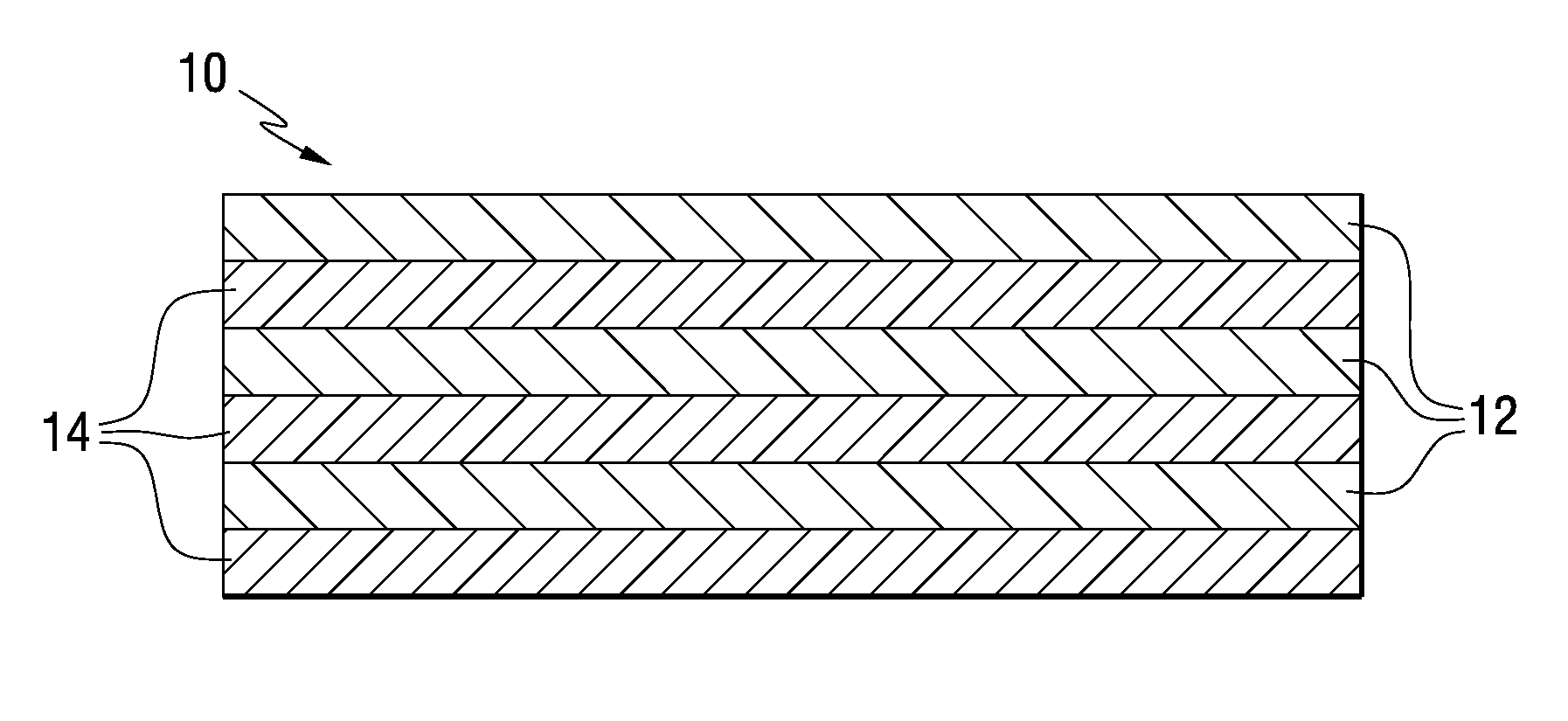
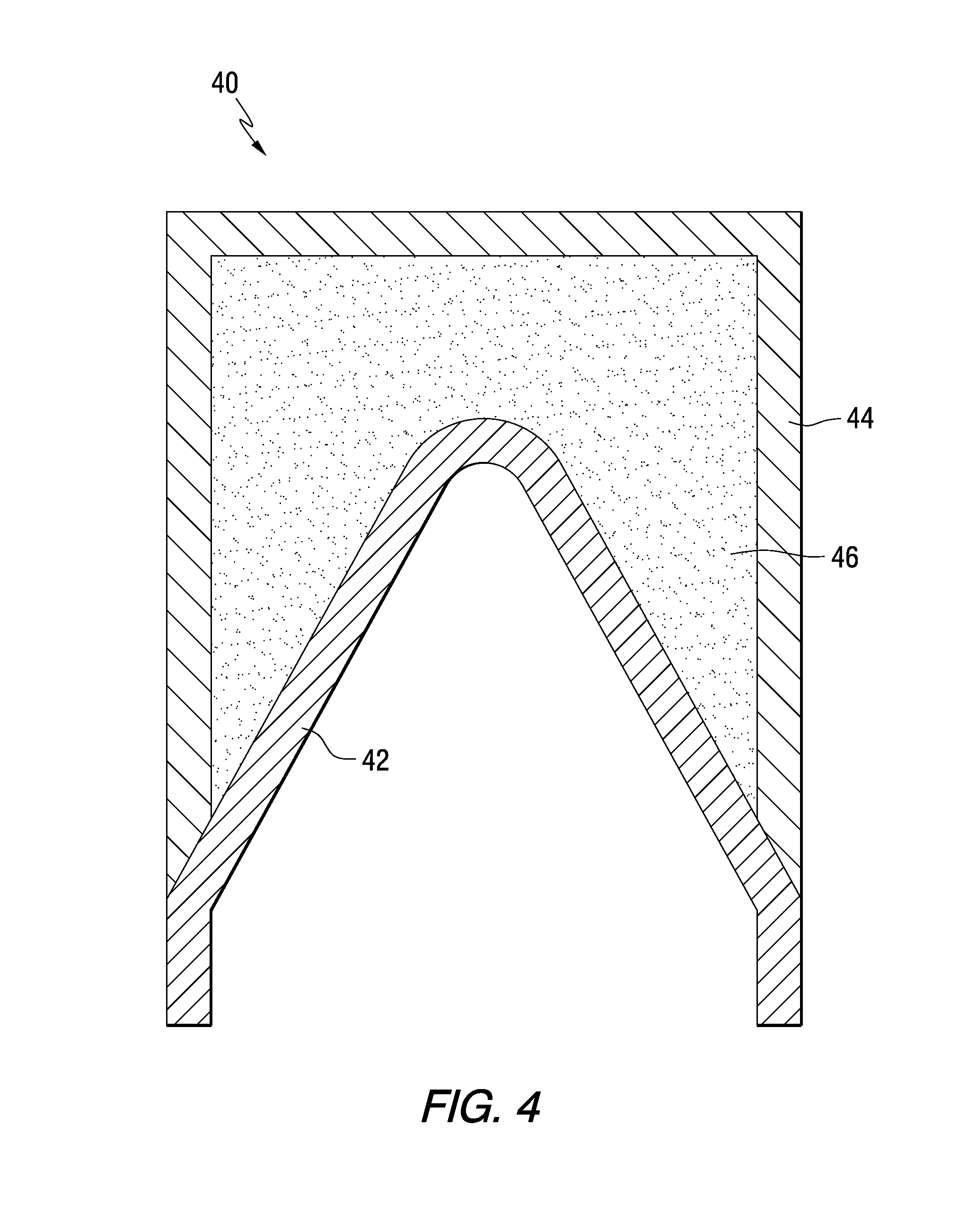
[0031]Samples comprising Ni / Al multilayers on copper cones were made. The multilayers were applied using a Magnetron sputtering process. This process is done in a vacuum chamber (<10-5 Torr) using sputter guns, plasma formation and large electrical potentials to dislodge atoms from a target material and deposit them on the substrate. The process occurs on the atomic level and deposition rates are influenced by factors such as applied voltage, distance from sputter target, substrate orientation, vacuum, etc. For this series of tests, alloys AA-1100 (99% Al) and Inconel 625 (61 Ni-22 Cr-2.5 Fe-9 Mo) were used as target materials.

[0032]Al / Ni coatings were formed on conical copper liners, and monolithic Al / Ni cones were formed on a mandrel and removed. However, as the coating trials progressed, it became evident that slow sputtering rates were associated with the latter. The time required to the requisite 0.048-inch thickness would have been long. Therefore, the efforts focused on coati...

example 2

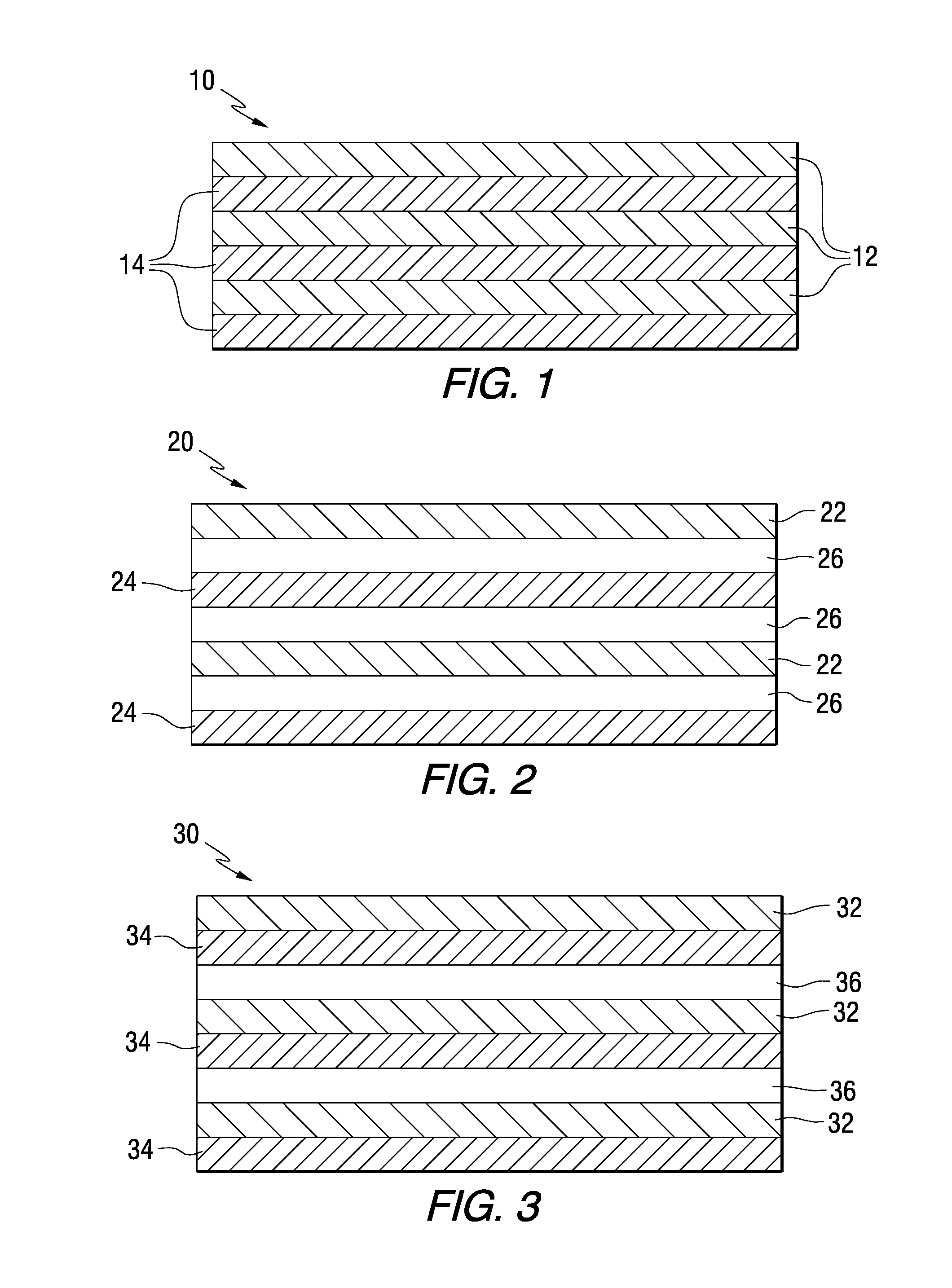
[0037]Two alloy systems were selected: nickel-aluminum and tantalum-aluminum. Two-inch cathodes (one of Ni and one of Al) are positioned in opposite directions, at a 2 inch distance from the substrate holder (drum), which rotates at an adjustable speed. The substrates to be deposited on are positioned on the rotating drum, and moved past each target sequentially. This allows deposition of the desired number of bi-layers, and desired total foil thickness, as determined by rotation speed, selected deposition rate, and total run time.

[0038]To establish predictable deposition rates for the materials, deposition onto precision gage blocks was made. This was done with one segment covered, that when removed after deposition left a sharp “step” from the gage block surface to the top of the deposited material. This was measured using a high sensitivity lever gage indicator with submicron resolution. Gage blocks were held on the substrate holder at a distance of 3 inches from source to substr...

example 3

[0065]Repeating equal layers of aluminum and Inconel were deposited onto copper foil substrates that were approximately 6″ tall×10″ wide×25 mils thick. A grid was established on the copper sheet using high-temperature, vacuum-compatible tape (Kapton tape / silicone adhesive) to create rectangles of multi-layer foil approximately 1″×2″ in size for the initiation testing. After processing, reactive foils with even alternating layers resulted in 17 mm thick foils for initiation testing. Very thin 100 micron thick Inconel / Al exothermic multilayer foils fabricated using the magnetron sputter deposition process achieved tensile strengths of 300 Mpa.

[0066]Differential scanning calorimetry was performed on freestanding multi-layer material (material removed from substrate prior to DSC run). This analysis measured heat flow as a function of scan temperature of several milligrams of each of the multi-layer sample materials. Specimens were subjected to a heating cycle that ramped from ambient te...


PUM

PropertyMeasurementUnit
thicknessaaaaaaaaaa
tensile yield strengthaaaaaaaaaa
temperaturesaaaaaaaaaa

Abstract

The invention provides shock initiation devices comprising multilayer structures with constituent layers that undergo an exothermic self-propagating reaction once initiated by shock. The multilayer structures may be used as components in shaped charges, EFP devices, warheads, munition casings, interceptors, missiles, bombs, and other systems. The reactive layer materials may be selected based on required structural properties, density and reaction temperature.

Description

CROSS-REFERENCE TO RELATED APPLICATIONS[0001]This application claims the benefit of U.S. Provisional Patent Application Ser. No. 60 / 473,509 filed May 27, 2003, which is incorporated herein by reference.[0002]This application is a continuation-in-part of U.S. application Ser. No. 10 / 839,638 filed May 5, 2004, which is incorporated herein by reference.GOVERNMENT CONTRACT[0003]The United States Government has certain rights to this invention pursuant to Contract No. DASG-60-02-0171 awarded by the U.S. Army Space Missile Defense Command, Contract No. N68936-03-C-0019 awarded by the U.S. Navy, and Contract No. F08630-02-SC-0048 awarded by the U.S. Air Force.FIELD OF THE INVENTION[0004]The present invention relates to reactive devices, and more particularly relates to shock initiation devices such as reactive shaped charges, munitions casings, kinetic interceptors and the like, which include reactive multilayer structures.BACKGROUND INFORMATION[0005]Exothermic warhead technology has been ...

Claims


Application Information

Patent Timeline
Patent Type & Authority Patents(United States)
IPC IPC(8): F42B1/032
CPCC06B45/14F42B1/032F42B39/00F42B12/76F42B12/06
Inventor LANGAN, TIMOTHYRILEY, MICHAEL A.
Owner SURFACE TREATMENT TECH INC
Why Eureka
Try Eureka