Guide wire

a technology of guide wire and guiding rod, which is applied in the field of transendoscopic guide wire, can solve the problems of difficult to provide the mark at the desired position, difficulty in confirming the axial movement of the guide wire, and limitations in the degree of freedom in the shape and width of the mark, so as to improve the visibility of the color developing portion, clear color difference, and high contrastability

Active Publication Date: 2007-10-09
TERUMO KK
View PDF29 Cites 31 Cited by
  • Summary
  • Abstract
  • Description
  • Claims
  • Application Information

AI Technical Summary

Benefits of technology

[0032]According to preferred aspects of the guide wire, because the guide wire has the color developing portion such as a marker while ensuring a relatively high contrastability under, for example, X-ray fluoroscopic guidance, the position or the like of the guide wire can be confirmed in a living body by observation through, for example, an endoscope. In particular, because the color developing portion can be configured as the visible marker having a desired shape and size formed at a desired position, it is possible to achieve improved visibility of the color developing portion. The visible marker representative of the color developing exhibits relatively clear color difference and brightness (contrast) with the matrix of the resin layer (cover layer) covering the core member, and is less susceptible to peeling, less lost due to dissolution, and less fading. Also, such a marker possessing relatively excellent visibility can be formed without the occurrence of substantial projection and recess.
[0033]Because the contrast agent contained in the resin layer, for example the first resin layer, is composed of a powder of a metal oxide, at the time of forming the color developing portion on the surface of the resin layer by irradiating the surface with laser light, the contrast agent is less altered (oxidized) or deteriorated, and generally does not cause any spark or the like. Accordingly, the degree of freedom in selection of the kind and irradiation intensity (energy) of laser light can be broadened to better clarify the color development of the color developing agent, thus improving the visibility of the marker.
[0034]The guide wire is preferably configured so that at the distal end portion of the guide wire, the flexibility is gradually increased in the direction toward the distal end. As a result, the distal end of the guide wire can be flexibly curved so that it is possible to inhibit or prevent the occurrence of kinking (sharp bending) of the guide wire, thus improving the operation and safety at the time of insertion of the guide wire in a living body via a catheter or the like.
[0035]Even if a bending force or torsional force is repeatedly applied to the guide wire, peeling of the cover layer and / or peeling of one of the first and second resin layers from the other at the overlapping portion is inhibited. In particular, in the case where the overlapping portion is configured such that the thickness of the first resin layer is gradually decreased in the direction toward the distal end and the thickness of the second resin layer is gradually increased in the direction toward the distal end, the change in flexibility of the guide wire at the overlapping portion and its neighboring region is smoothened and the adhesion between the first resin layer and the second resin layer is increased.
[0036]In the case where a contrastability is imparted to the distal end portion of the guide wire, or a contrastability higher than that of another portion is imparted to the distal end of the guide wire, the position of the guide wire in a living body, particularly the position of the distal end of the guide wire in a living body, can be relatively easily confirmed from outside of the living body.
[0037]With the outer surface of the guide wire coated with the hydrophilic lubricating coating and / or the hydrophobic lubricating coating, it is possible to more smoothly and safely perform operation of the guide wire at the time of insertion or removal of the guide wire.

Problems solved by technology

During insertion of a guide wire, if the guide wire is monochromatic, it is difficult to confirm the axial movement of the guide wire.
However, this method using a hollow tube has disadvantages in that because the mark (colored stripe patterns) is provided simultaneously with the formation of the guide wire, it is difficult to provide the mark at a desired position.
Also, there are limitations with respect to the degree of freedom in the shape and width of the mark.
A method which utilizes printing, however, has disadvantages in that because the ink has little or no resistance against solvent, it is difficult to coat the surface of a guide wire with a lubricating layer made from a hydrophilic polymer or the like after formation of the mark on the surface of the guide wire.
In addition, it is difficult to form the mark on a curved surface of the guide wire, and the ink takes a relatively long time to dry and is liable to flow in a living body during use of the guide wire.
This improved method, however, has its own disadvantages because it requires additional steps of drying ink and forming the coating layer, thereby complicating the production process.
In addition, there is a limitation in design in that only a transparent resin is used for forming the coating layer.
This method of forming a temper color mark on the surface of the guide wire by heating is disadvantageous in that it can be applied only to a catheter introducing wire made from a steel material.
For example, the physical properties of a superelastic alloy (Ni—Ti alloy) generally used as the material of a core member of a guide wire are liable to be changed by heat-treatment such as heating and so this method is not well suited to being applied to a guide wire having a core member made from such a superelastic alloy.
However, the formation of a mark by stamping is not well suited to providing a raised marked portion while the formation of a mark by irradiation with laser light is not well suited to providing a recessed marked portion.
This method thus has similar problems to those mentioned above in connection with the methods discussed in U.S. Pat. No. 5,379,779 and Japanese Utility Model Laid-open No.

Method used


Image

  • Guide wire
  • Guide wire
  • Guide wire

Examples


first embodiment

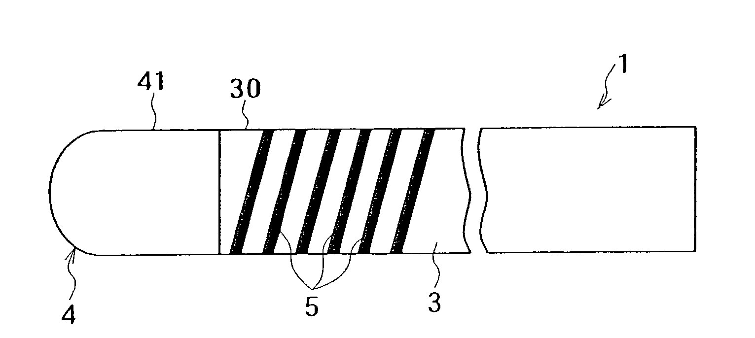
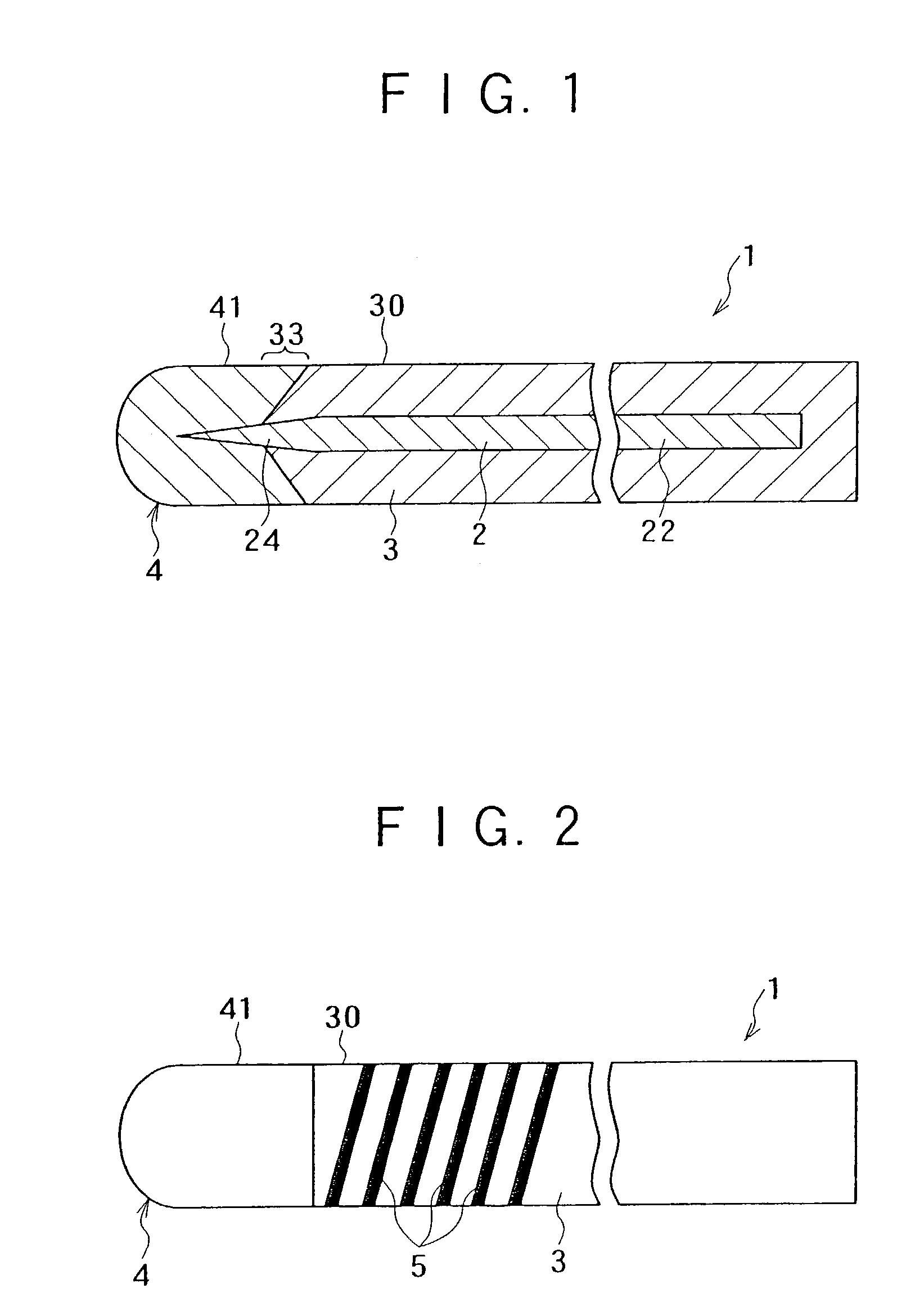
[0049]FIGS. 1 and 2 illustrate a guide wire. For purposes of convenience of description, the right side and the left side in FIGS. 1 and 2 are referred to as the “proximal end side” and “distal end side” respectively.

[0050]Referring to FIG. 1, a guide wire 1 according to a first embodiment includes a linear core member 2 and a resin layer or cover layer 3. The resin layer or cover layer 3 is formed to cover at least part of the core member 2.

[0051]The core member 2 extends nearly over the entire length of the guide wire 1 and includes a main body portion 22 corresponding to a main body portion of the guide wire 1 and a taper portion 24 positioned at the distal end side of the guide wire 1. The main body portion 22 has a substantially constant diameter, while the taper portion 24 is tapered such that the outer diameter of the taper portion 24 is gradually reduced in the direction toward the distal end.

[0052]The taper portion 24 is advantageous in gradually increasing the flexibility ...

second embodiment

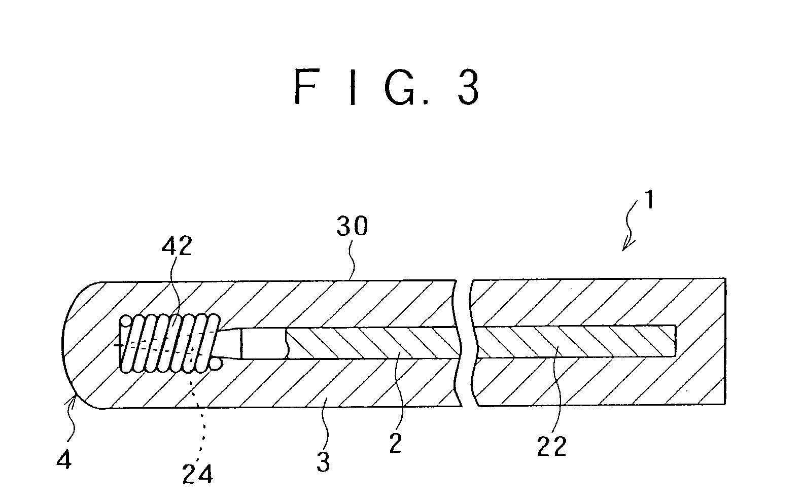
[0101]The contrasting portion 4 of the guide wire 1 is composed of a metal member 42 having a contrasting function. The metal member 42 surrounds at least part of a taper portion 24 of the core member 2. As shown in FIG. 3, the metal member 42 is formed to possess a coil shape, although it may be formed to possess other shapes such as a ring shape. In particular, the metal member 42 may be composed of a plurality of ring-shaped metal member parts adjacently arranged in the longitudinal direction of the core member 2.

[0102]The metal member 42 is made from, for example, tungsten or a noble metal such as gold or platinum. Among these examples of materials, tungsten is preferred.

[0103]The distal end portion of the guide wire 1 provided with the metal member 42 exhibits a good contrasting function.

[0104]According to this embodiment, because the resin layer 3 is formed to substantially cover the entire length of the core member 2 from the proximal end to the distal end of the core member...

seventh embodiment

[0156]The guide wire 1 includes a linear core member 2 having a main body portion 22 possessing a nearly constant outer diameter and a taper portion 24 provided on the distal end side from the main body portion 22. Like previous embodiments, a cover layer 3 is provided on the outer periphery of the core member 2. The cover layer 3 includes a first resin layer 31 and a second resin layer 32, with the second resin layer being positioned on the distal end side from the first resin layer 31. The second resin layer 32 is made from a material having a flexibility higher than the flexibility of the material forming the first resin layer 31.

[0157]At an overlapping portion 33 at which the distal end portion of the first resin layer 31 overlaps the proximal end portion of the second resin layer 32, the first resin layer 31 is covered by the second resin layer 32. Further, at the overlapping portion 33, the thickness of the first resin layer 31 is decreased in the direction toward the distal ...


PUM


Abstract

A guide wire is configured to have a less lossy marker formed at a desired position and providing a relatively high degree of contrastability under X-ray fluoroscopic guidance or the like. The guide wire includes a linear core member, a resin layer covering a main body portion of the core member, and a contrasting portion covering the distal end portion of the core member. The resin layer contains a color developing agent which develops color by laser light irradiation, and a contrast agent composed of a metal oxide powder. The contrasting portion is made from a resin containing a contrast agent composed of a metal powder and has a contrasting function higher than the resin layer. A visible marker is formed on the outer surface of the resin layer through color development of the color developing agent by irradiating the surface of the resin layer with laser light.

Description

[0001]This application is based on and claims priority under 35 U.S.C. § 119 with respect to Japanese Application No. 2002-82997 filed on Mar. 25, 2002 and Japanese Application No. 2002-367390 filed on Dec. 18, 2002, the entire content of both of which is incorporated herein by reference.FIELD OF THE INVENTION[0002]The present invention generally relates to a guide wire. More particularly, the present invention pertains to a transendoscopic guide wire adapted to be inserted in a living body by way of an endoscope.BACKGROUND OF THE INVENTION[0003]In the observation and treatment of a biological lumen or the like using an endoscope, a guide wire is employed to introduce the endoscope or a catheter inserted in a lumen of the endoscope to a specific position in the biological lumen or the like.[0004]During insertion of a guide wire, if the guide wire is monochromatic, it is difficult to confirm the axial movement of the guide wire. It is thus preferable to provide a mark on the surface ...

Claims


Application Information

Patent Timeline
Patent Type & Authority Patents(United States)
IPC IPC(8): A61B5/00A61M25/00A61M25/01A61M25/09
CPCA61M25/09A61M2025/09166A61M2025/09075A61M2025/0008
Inventor IWAMI, JUNTAMAI, NORIYUKI
Owner TERUMO KK
Why Eureka
Try Eureka