Method for oxy-fuel combustion

a combustion system and oxy-fuel technology, applied in the direction of combustion using lumps and gaseous fuels, indirect carbon-dioxide mitigation, combustion using lumps and liquid fuels, etc., can solve the problems of system production of nox and other green-house gases, structural and material limitations dictate the upper temperatures to which many industrial systems can be subjected, and the use of lumps and gaseous fuels is quite limited, so as to reduce the consumption of fuel and reduce the use of gas

Inactive Publication Date: 2007-10-16
JUPITER OXYGEN CORP
View PDF17 Cites 18 Cited by
  • Summary
  • Abstract
  • Description
  • Claims
  • Application Information

AI Technical Summary

Benefits of technology

[0012]An oxygen fueled combustion system includes a furnace having a controlled environment, and includes at least one burner. The combustion system includes an oxygen supply for supplying oxygen having a predetermined purity and a carbon based fue...

Problems solved by technology

Oxygen fueled burner systems are known, however, their use is quite limited.
Otherwise, it is commonly accepted that structural and material limitations dictate the upper temperatures to which many industrial systems can be subjected.
One drawback to the use of air fueled combustion systems, is that these systems produce NOx and other green-house gases such as carbon dioxide, sulfur dioxide and the like, as an inherent result of the combustion process.
NOx and other green-house gases are a large contributor to environmental pollution, including, but not limited to acid rain.
As such, the reduction in emission of NOx and other green-house gases is desirable, and as a result of regulatory restrictions, emission is greatly limited.
Another drawback with respect to air fueled furnaces is that much of the energy released from the combustion process is absorbed or used to heat the gaseous nitrogen present in the air that is fed to the furnace.
This energy is essentially wasted in that the heated nitrogen gas is typically, merely exhausted from the heat source, e.g., furnace.
In addition, electric furnaces require a con...

Method used


Image

  • Method for oxy-fuel combustion
  • Method for oxy-fuel combustion
  • Method for oxy-fuel combustion

Examples


Embodiment Construction

[0046]While the present invention is susceptible of embodiment in various forms, there is shown in the drawings and will hereinafter be described a presently preferred embodiment with the understanding that the present disclosure is to be considered an exemplification of the invention and is not intended to limit the invention to the specific embodiment illustrated. It should be further understood that the title of this section of this specification, namely, “Detailed Description Of The Invention”, relates to a requirement of the United States Patent Office, and does not imply, nor should be inferred to limit the subject matter disclosed herein.

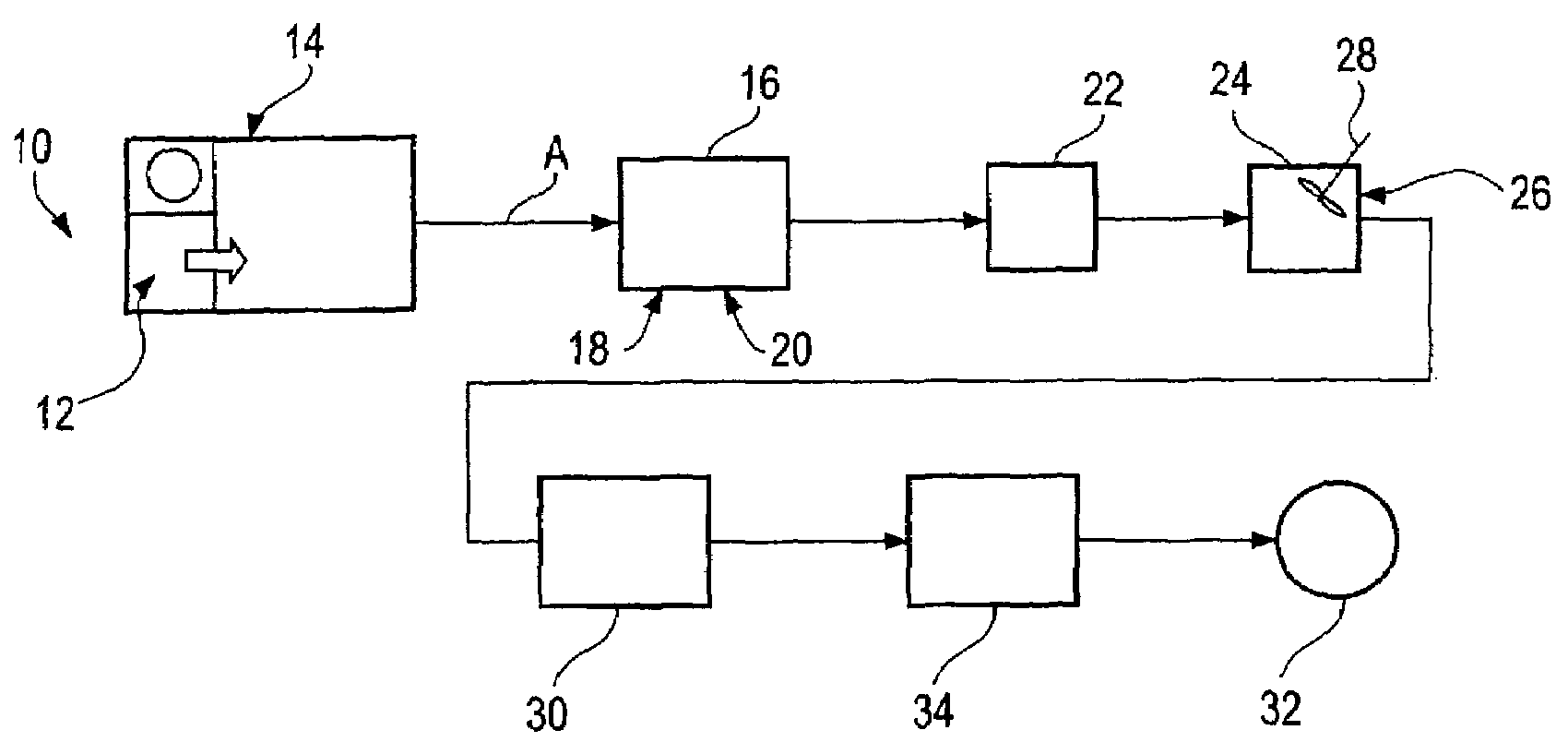
[0047]An oxy-fuel combustion system uses essentially pure oxygen, in combination with a fuel source to produce heat, by flame production (i.e., combustion), in an efficient, environmentally non-adverse manner. Oxygen, which is supplied by an oxidizing agent, in concentrations of about 85 percent to about 99+ percent can be used, however, it i...


PUM

PropertyMeasurementUnit
Fractionaaaaaaaaaa
Fractionaaaaaaaaaa
Fractionaaaaaaaaaa

Abstract

An oxygen fueled combustion system includes a furnace having at least one burner, an oxygen supply for supplying oxygen having a predetermined purity, and a carbon based fuel supply for supplying a carbon based fuel. The oxygen and the carbon based fuel are fed into the furnace in a stoichiometric proportion to one another to limit an excess of either the oxygen or the carbon based fuel to less than 5 percent over the stoichiometric proportion. The combustion of the carbon based fuel provides a flame temperature in excess of 4500° F. The exhaust gas stream from the furnace has substantially zero nitrogen-containing combustion produced gaseous compounds from the oxidizing agent and reduced green-house gases. Substantially less carbon based fuel is required than conventional combustion systems without a loss of energy output.

Description

CROSS-REFERENCE TO RELATED APPLICATION DATA[0001]This application is a continuation of U.S. patent application Ser. No. 10 / 161,230, filed Jun. 3, 2002, now U.S. Pat. No. 6,596,220 which is a divisional application of U.S. patent application Ser. No. 09 / 843,679, filed Apr. 27, 2001, now U.S. Pat. No 6,436,337.BACKGROUND OF THE INVENTION[0002]The present invention pertains to an oxygen fueled combustion system. More particularly, the present invention pertains to an oxy-fueled combustion system in which the production of green-house gases is reduced and in which fossil fuel consumption is reduced.[0003]Oxygen fueled burner systems are known, however, their use is quite limited. Oxy-fueled burner systems are generally only used in those applications in which extremely high flame temperatures are required. For example, these systems may be used in the glass making industry in order to achieve the temperatures necessary to melt silica to a fusion temperature. Otherwise, it is commonly ac...

Claims


Application Information

Patent Timeline
IPC IPC(8): F23C5/00F23C99/00C22B1/00C22B7/00C22B9/02C22B9/16C22B21/00F23D14/32F23G5/00F23G5/08F23G7/00F27B3/10F27D7/02F27D7/06F27D17/00F27D19/00F27D21/00F27D99/00
CPCC22B9/16C22B21/0092F27D19/00F27D21/0014F27D99/0033Y10S588/90F27D2019/0034F27D2019/0043Y02E20/12Y10S266/901Y10S266/90F27D2019/0003Y02P10/143C22B7/003F27B3/20Y02P10/20C22B21/00Y02E20/34
Inventor GROSS, DIETRICH M.
Owner JUPITER OXYGEN CORP
Why Eureka
Try Eureka