Large mode area fiber for low-loss transmission and amplification of single mode lasers

a single-mode laser and fiber-to-mode technology, applied in the field of optical fiber design, can solve the problems of system power loss, system power loss, and signal loss of all optical fibers, and achieve the effect of more reliable and cost-effective coupling and larger fiber-to-mode area

Active Publication Date: 2007-10-16
IPG PHOTONICS CORP
View PDF10 Cites 76 Cited by
  • Summary
  • Abstract
  • Description
  • Claims
  • Application Information

AI Technical Summary

Benefits of technology

[0027]Another object of the present invention is the provision for an optical fiber that enables the use of a more reliable and cost effective coupling due to a larger fiber effective mode area.

Problems solved by technology

However, a major limitation to the application of high-power fiber lasers in industrial applications is power loss due to non-linear effects as the beam propagates through the delivery fiber from the fiber laser source to the work area.
It is through this delivery fiber that the system can experience significant power loss due to non-linear effects within the current delivery fiber designs.
All optical fibers experience some signal loss due to attenuation and non-linearities within the fiber itself.
However, as the numerical aperture decreases the guidance of the fiber weakens and significant losses can arise from small imperfections of the fiber or from bending.
Moreover, the fiber may no longer strictly propagate in single-mode, as some higher-order modes may also propagate with relatively small losses.
Nevertheless, large mode area single mode fibers have typically been limited to an effective mode area of about 615 μm2 (28 μm mode field diameter).
As a result, robust single-mode propagation in PCFs has also been limited to a MFD of approximately 28 μm, a level similar to that of conventional fiber, which is not surprising considering the similarity in the principle behind the two approaches.

Method used


Image

  • Large mode area fiber for low-loss transmission and amplification of single mode lasers
  • Large mode area fiber for low-loss transmission and amplification of single mode lasers
  • Large mode area fiber for low-loss transmission and amplification of single mode lasers

Examples


Embodiment Construction

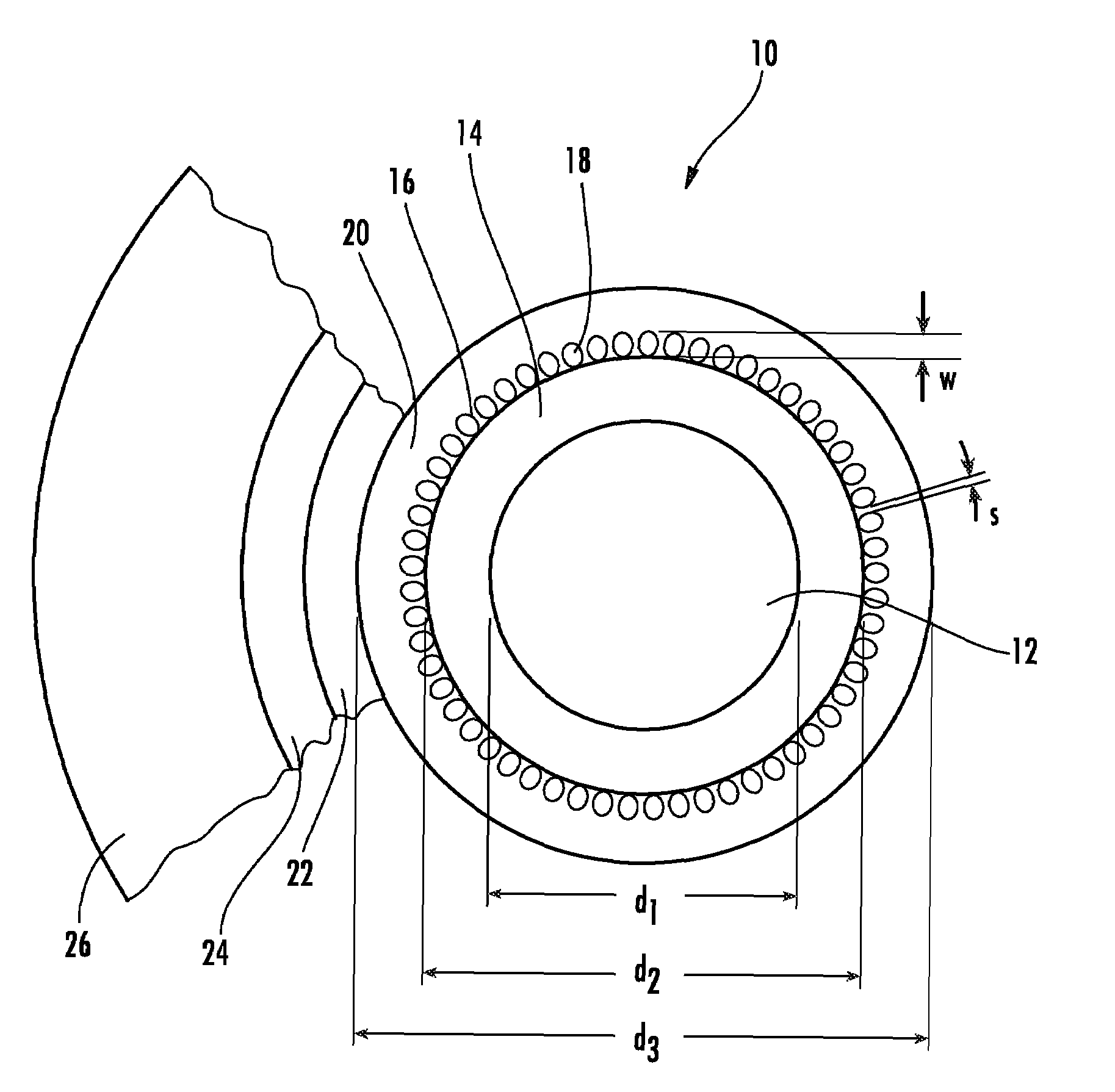
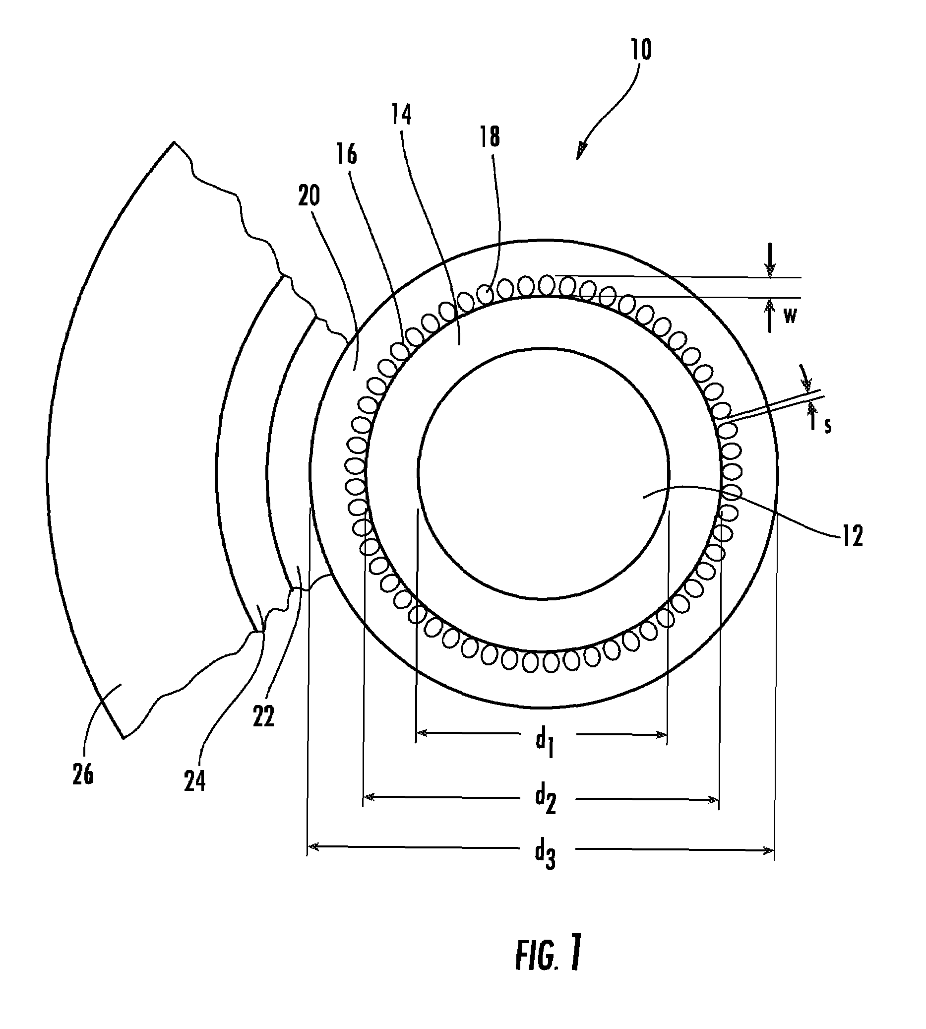
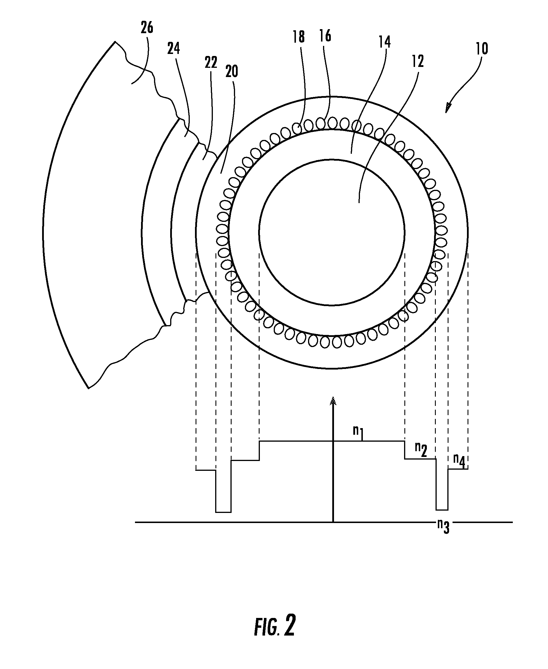
[0038]Referring to FIGS. 1-3, the preferred embodiment of the optical fiber of the present invention is illustrated and generally at 10.

[0039]As shown in its preferred embodiment, the fiber 10 comprises a photonic crystal fiber with an air hole cladding layer. In general, photonic crystal fibers with hole structures are known in the art. Photonic crystal fibers are generally constructed from undoped silica glass. As noted above, guiding is provided by spaced hole structures within the crystal structure of the fiber. Selected portions of the silica glass may contain doping to vary the refractive index.

[0040]More specifically, the optical fiber 10 of the present invention includes a large diameter core (up to 60 μm) 12, and a first cladding 14 wherein the difference between refractive index in the core 12 and the first cladding 14 is very small (Δn<0.002) (low contrast boundary), thus providing a very low numerical aperture core (NA between 0.02 and 0.06).

[0041]The fiber 10 further ha...


PUM


Abstract

A large mode area optical fiber includes a large diameter core (d1 up to 60 μm), and a first cladding (diameter d2) wherein the difference between refractive index (n1) in the core and the first cladding (n2) is very small (Δn<0.002), thus providing a very low numerical aperture core (NA1 between 0.02 and 0.06). The preferred ratio of d2/d1<2. The fiber further has a second cladding, preferably a layer of air holes, having a very low refractive index n3 as compared to the core and first cladding such that the first cladding has a relatively high numerical aperture (NA2>0.4) (n3 is preferably less than 1.3). The small change in refractive index between the core and inner cladding combined with a large change in refractive index between the first cladding and second cladding provides a significantly improved single mode holding waveguide.

Description

BACKGROUND OF THE INVENTION[0001]1. Field of the Invention[0002]The present invention relates generally to optical fiber design and more particularly an optical fiber having a very large mode field core.[0003]2. Background of the Related Art[0004]High-power single-mode fiber lasers having output power in the range of 1-50 kW are now coming into widespread use in the industrial fields of welding, high-speed cutting, brazing, and drilling. Fiber lasers have high wall plug power efficiency, and very good beam characteristics. The beam from fiber lasers can be focused to small spot sizes with long focal length lenses with consistent beam properties independent of power level or pulse duration. Ytterbium single-mode fiber lasers with an M2 of 1.1 have continually increased in power to the multi-kW level, and can be focused to 10-15 μm spot diameters with perfect Gaussian distribution. Further increasing power will open up additional markets in the future.[0005]However, a major limitation...

Claims


Application Information

Patent Timeline
Patent Type & Authority Patents(United States)
IPC IPC(8): G02B6/36H01S3/00
CPCG02B6/02009G02B6/02366G02B6/0365G02B6/03666G02B6/02361H01S3/1618G02B6/03688H01S3/06729H01S3/06741H01S3/0675
Inventor GAPONTSEV, VALENTIN P.VYATKIN, MIKHAILGRIGORIEV, VLADIMIR
Owner IPG PHOTONICS CORP
Why Eureka
Try Eureka