[0009]One aspect of the present invention provides a magnet assembly that can be employed as part of a
linear motor stage to form a high performance
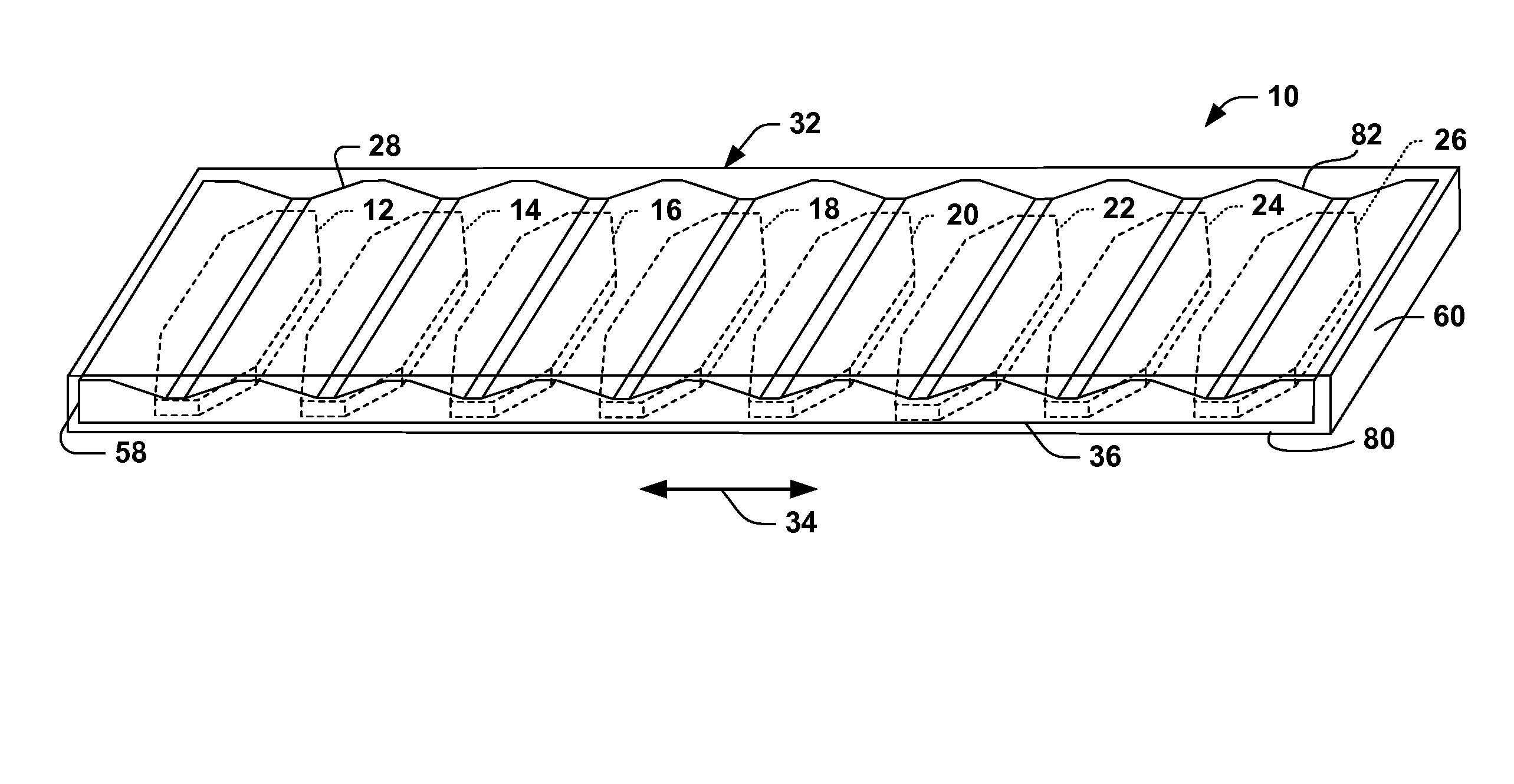
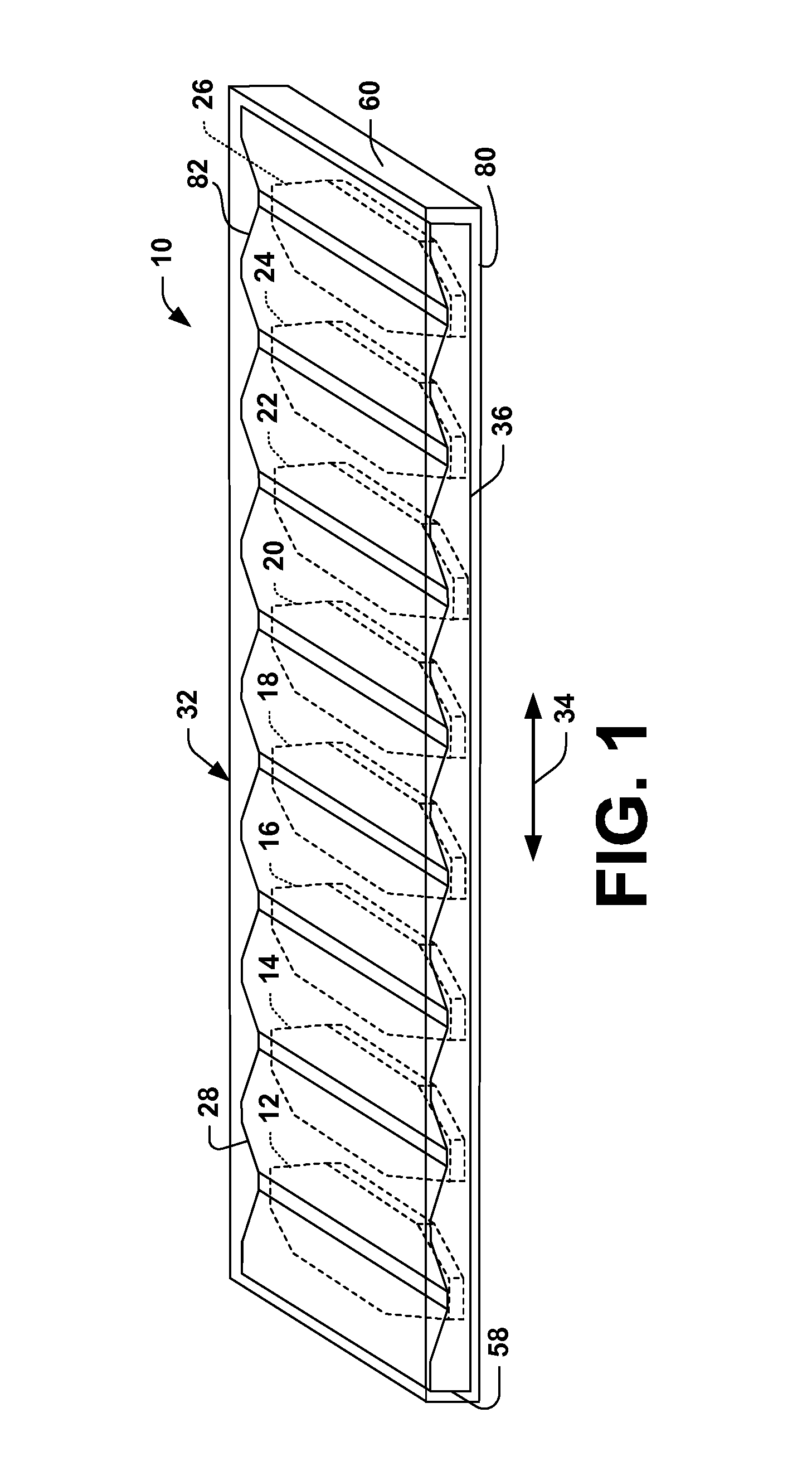
linear motor. The magnet assembly includes a plurality of magnets operatively associated with magnetically conductive plate, commonly known as a back iron. The magnets extend from a common side of the back iron. The back iron is dimensioned and configured to substantially conform to
magnetic flux that travels through the back iron when the magnet assembly is exposed to a
magnetic field, such as from windings of a motor path. In one particular aspect of the present invention, a cross-sectional dimension of the back iron varies between opposed ends of the back iron as a function of the position and / or orientation of the magnets. For example, a thickness of the back iron is greater at locations between adjacent pairs of the magnets than at locations generally centered with the respective magnets. As a result of such back iron geometry,
force output to moving
mass ratio of a motor incorporating the magnet assembly is improved over conventional configurations of magnet assemblies. Also, the back iron geometry reduces leakage flux.
[0010]Another aspect of the present invention provides a linear
motor system that includes a path having a plurality of windings, which can be energized to produce desired magnetic fields. The linear
motor system also includes a magnet assembly, such as described above. The linear
motor system achieves high performance because the magnet assembly has a
reduced mass, which substantially conforms to magnet
flux lines that travel through the magnet assembly during energization of path windings. The mass further can be reduced by employing generally elongated octagonal magnets, such as by removing corner portions from rectangular magnets.
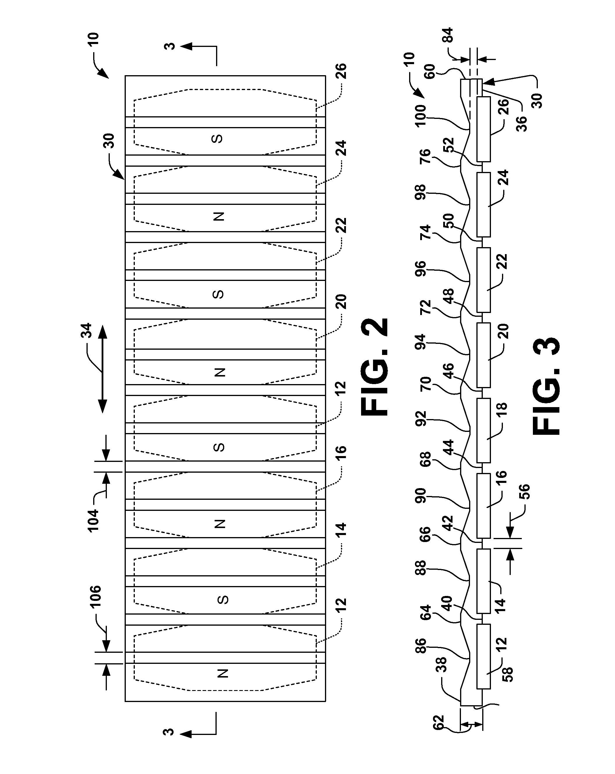
[0011]According to yet another aspect, a magnet assembly can be used in a linear motor arrangement in such a way so as to generate a
Halbach array. A
Halbach array can be achieved by a special formation of magnets using 90-degree angles to direct each individual magnet's field in alternating vertical and horizontal orientations, such that half of the magnets are vertically polarized (e.g., perpendicular to a direction of motion of the linear motor), while the other half of the magnets are horizontally polarized, permitting maximization of the
magnetic field produced thereby in a desired direction. Additionally, remnant fields that do not contribute to
force output in a horizontal direction can be cancelled. This magnet arrangement can be formed as a
reduced mass magnet assembly as described above, and can further concentrate
magnetic flux in a desired direction while simultaneously mitigating the effects of stray magnetic fields.
[0012]According to another aspect, a platen and forcer
system is provided. The
system employs the reduced mass magnet assembly as previously described. Additionally or independently, other features of the forcer system are modified so as to further optimize
magnetic flux capacity in a desired direction. For example, the system can comprise magnetically conductive backing materials fashioned from
solid stock, laminations, and / or combinations of smaller stock, or by other known means, such as as
sintering, etc., with a varied cross-sectional thickness comprising peaks and valleys, and a plurality of magnets associated therewith such that the center of each magnet is generally aligned with a valley (e.g., a relatively thinner region of the
metal backing). The plurality of magnets can be arranged to generate a Halbach array that maximizes output force in a desired horizontal direction and minimizes and / or cancels magnetic fields that do not contribute to force output in the desired horizontal direction. Furthermore, the platen and forcer system mitigates shielding requirements when employed in conjunction with the Halbach array magnet arrangement, making the system highly suitable for manufacturing applications such as e-beam
lithography,
focused ion beam systems, and the like. For instance, an
electron beam employed to etch, inspect, and / or otherwise fabricate a
semiconductor wafer can be adversely affected by stray static and alternating magnetic fields, which results in intricate shielding requirements and its complex design when traditional platen and forcer systems are employed. To mitigate a need for elaborate shielding, the subject systems and methods can employ the Halbach magnet arrangement, which can facilitate reducing costs and improving
throughput in such fabrication environments. It will be appreciated that any type of linear motor (e.g., iron core motors, ironless motors, . . . ) can be utilized in conjunction with the various aspects set forth herein.

