Method and system for coating internal surfaces of prefabricated process piping in the field

a technology of prefabricated process piping and internal surfaces, which is applied in the field of coating piping systems, can solve the problems of multiple ionizing collisions and a more intense plasma, and achieve the effect of increasing the magnitude of bias and improving the adhesion of dl

Active Publication Date: 2007-11-27
AGM CONTAINER CONTROLS
View PDF14 Cites 104 Cited by
  • Summary
  • Abstract
  • Description
  • Claims
  • Application Information

AI Technical Summary

Benefits of technology

[0017]A further advantage of the invention is that a multi-step process can be used to tailor the film qualities deposited on the internal surface of the welded workpiece. The surface of the workpiece can also be pre-cleaned by the introduction of a sputtering gas such as Ar in the first step of the method, following pump down to 1×10⁻³ Torr pressure or preferably 1×10⁻⁴ Torr. Contaminants on the interior surface of the workpiece are sputtered off when the negative DC pulse is applied. A second step can then be performed using carbon implantation to form a subsurface carbon layer in the steel. This layer improves the adhesion of the DLC. This is done by increasing the magnitude of the bias to greater than 5 kV. Care must be taken at this step for small diameter tubes, so that the size of the plasma sheath does not become larger than the radius of the tube. The formula for the smallest radius of a cylinder for which the sheaths do not overlap is as follows:
[0018]d=4⁢ɛ⁢⁢Venwhere V is the magnitude of the voltage, and n is the plasma density.
[0019]Following this implantation step, DLC deposition steps are performed using the above-mentioned methane, acetylene or toluene precursors. The DC pulse voltage is reduced in this process step to provide thin film deposition instead of implantation (e.g., 100 V-10 kV). Argon is also mixed with the carbon-containing precursors during these coating steps. In one embodiment of the invention, to control sputtering versus deposition rate and thus provide a more uniform coating down the tube, coating material is continuously sputtered off the entrance portion of the tube, wherein the sputtered material is drawn by flow velocity toward the rear end of the tube. Uniformity is also controlled by the duty cycle of the DC pulse, such that when the pulse is “off,” the source gas is allowed to replenish and flow down the tube. One skilled in the art will recognize that uniformity is also controlled by the selections of the gas flow rate and the pumping speed.

Problems solved by technology

This pressure is such that the electron mean free path is slightly less than the diameter of the tube, causing electrons to oscillate across the tube and resulting in multiple ionizing collisions and a more intense plasma.

Method used


Image

  • Method and system for coating internal surfaces of prefabricated process piping in the field
  • Method and system for coating internal surfaces of prefabricated process piping in the field
  • Method and system for coating internal surfaces of prefabricated process piping in the field

Examples


Embodiment Construction

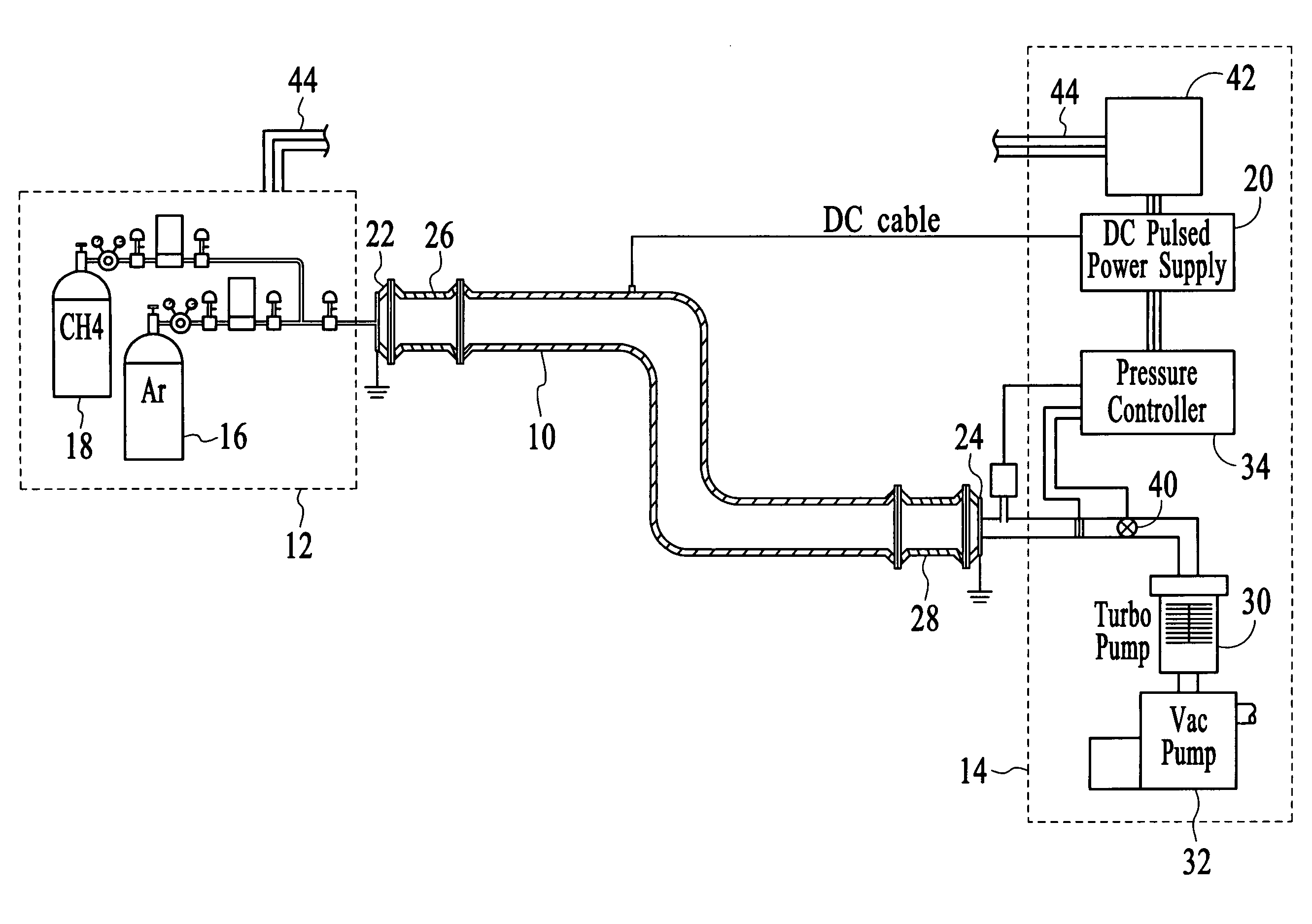
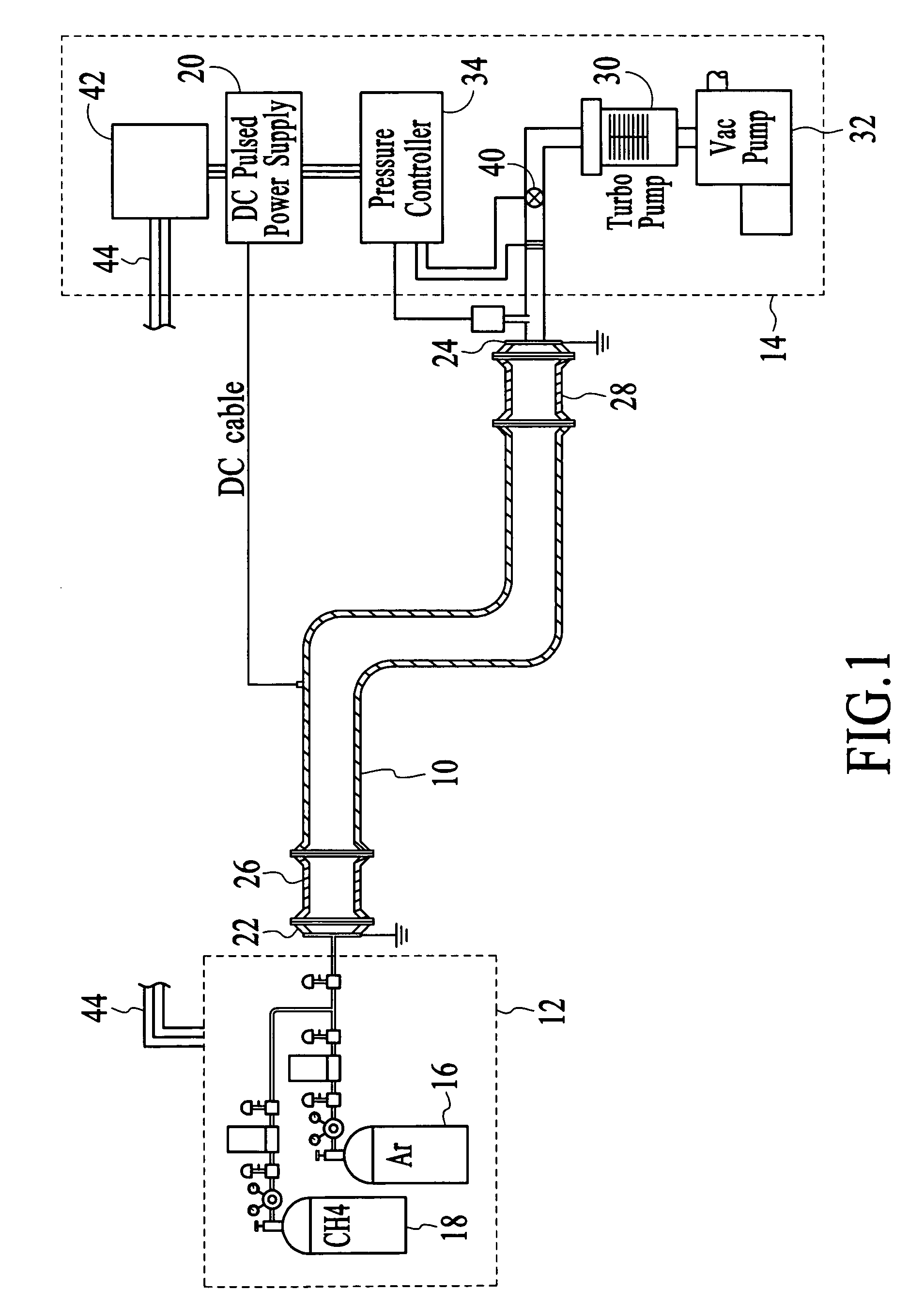
[0023]With reference to FIG. 1, a conductive piping, or “workpiece,”10 is shown as being connected to a system that includes a gas supply subsystem 12 and a process control subsystem 14. The workpiece is shown as a single piece, but may be an assembly of tubes or pipes. The assembly should have all welding and assembly steps completed and should be leak tested prior to the coating process to be described below. A readily available non-toxic carbon containing gas, such as methane or acetylene, is provided by a first gas supply container 16. This gas is used to form a diamond-like carbon (DLC) coating on the inside of the workpiece. Argon (or other sputter gas) is provided from a second gas supply container 18 to allow plasma “pre-cleaning” of the pipe surface, and mixing of Ar and carbon-containing gas.

[0024]A DC pulsed power supply 20 is used to apply a negative bias to the workpiece 10. This bias is used to (a) create a plasma between a cathode and a grounded anode, (b) draw an ion...


PUM

PropertyMeasurementUnit
pressureaaaaaaaaaa
pressureaaaaaaaaaa
pressureaaaaaaaaaa

Abstract

The coating of internal surfaces of a workpiece is achieved by connecting a bias voltage such that the workpiece functions as a cathode and by connecting an anode at each opening of the workpiece. A source gas is introduced at an entrance opening, while a vacuum source is connected at an exit opening. Pressure within the workpiece is monitored and the resulting pressure information is used for maintaining a condition that exhibits the hollow cathode effect. Optionally, a pre-cleaning may be provided by introducing a hydrocarbon mixture and applying a negative bias to the workpiece, so as to sputter contaminants from the workpiece using argon gas. Argon gas may also be introduced during the coating processing to re-sputter the coating, thereby improving uniformity along the length of the workpiece. The coating may be a diamond-like carbon material having properties which are determined by controlling ion bombardment energy.

Description

TECHNICAL FIELD[0001]The invention relates generally to plasma enhanced chemical vapor deposition systems and more specifically to coating piping systems in the field.BACKGROUND ART[0002]Often the assembly of the various components of a piping system adversely affects the properties of the material used for piping. For example, welding of the high purity 316L stainless steel tubing used to supply process gas for semiconductor manufacturing equipment can change the properties of the stainless steel. The change is due to heating and vapor plume effects, such that when the gasline is filled with a corrosive gas (e.g., SiCl2H2), it is usually the heat effected zone (welded area) that is most likely to exhibit corrosion failure. This is also true for the exhaust piping that forms the path from pumps to scrubbers.[0003]Much effort has been expended in improving the corrosion resistance of specialty metal alloys, for example stainless steel, by precisely defining chemistry levels (e.g., 16...

Claims


Application Information

Patent Timeline
Patent Type & Authority Patents(United States)
IPC IPC(8): C23C16/00C23C14/35
CPCC23C16/045C23C16/26C23C16/505C23C16/503C23C16/4401
Inventor BOARDMAN, WILLIAM JOHNTUDHOPE, ANDREW WILLIAMMERCADO, RAUL DONATE
Owner AGM CONTAINER CONTROLS
Why Eureka
Try Eureka