Tracking auto focus system

a technology of auto-focusing and tracking, which is applied in the direction of instruments, optical elements, mountings, etc., can solve the problems of over- or under-etching, affecting the electrical and/or optical performance of the final lcd product, and unavoidable defects, etc., and achieves the effect of eliminating the auto-focusing tim

Inactive Publication Date: 2007-11-27
PHOTON DYNAMICS
View PDF6 Cites 24 Cited by
  • Summary
  • Abstract
  • Description
  • Claims
  • Application Information

AI Technical Summary

Benefits of technology

[0021]In accordance with the present invention, a microscope is continuously maintained in focus to eliminate the auto-focusing time that would otherwise be required. The in-focus position is maintained so long as the microscope is pointed at a target plate, such as a TFT array undergoing inspection, and regardless of whether the microscope is stationary or in motion.
[0023]The actuator is adapted to adjust the distance between the microscope's objective lens and the target and includes, in part, an amplifier, a linear motor, and a linear encoder which provides positional feedback. The auto-focus sensor together with the ADC and signal conditioner are adapted to continuously monitor and detect the distance between the microscope's objective lens and the target and to supply the measured distance to the amplifier. The PID controller together with the DAC stabilizes the distance separating the microscope's objective lens and the target so as to maintain the best focus.

Problems solved by technology

During each of these stages and at various steps within each stage, many production defects may occur that may affect the electrical and / or optical performance of the final LCD product.
Other defects include mask problems, and over or under etching.
Even though the TFT deposition processes are tightly controlled, defect occurrence is unavoidable.
This limits the product yield and adversely effects production costs.
Commonly AOI and AC systems provide defect coordinates; they do not provide high resolution images required to classify defects as killer, repairable or just imperfections not affecting the TFT array performance (so called process defects).
Maintaining such Z position of the plate relative to the inspection or repair optics is difficult because of, for example, (a) the relatively large plate size, (b) the variations in plate thickness, (c) non-zero Z variations in the inspection / repair stage as it moves in X and Y, and (d) non-zero Z variations in plate holder (chuck) over the expanse of the plate.
During this period, the instrument is neither used for defect review nor for laser trimming and thus the instrument remains idle.
With typically 400 defects per plate, the auto-focusing consumes approximately 400 seconds of instrument idle time.
The idle time undermines the efficiency of instrument utilization.
The DIP based auto-focusing method is relatively simple and inexpensive and requires no additional hardware; however, it suffers from a number of number of deficiencies, a few of which are described below.
Therefore, the DIP method fails on blank or almost blank images.
Second, a single sample of the FQC does not indicate whether the microscope is above or below the best focus point.
Also, a single sample of FQC is insufficient to determine the distance that will achieve the best focus position.
Thus, even multiple samples of FQC often do not indicate the direction towards the best focus position.
As is well known, the DIP method, notwithstanding the above developments, is slow, and depending on the required auto-focus range and the CCD camera frame rate, may take 1 to 5 seconds to complete the auto-focusing task.
However, even with the optimized search, an auto-focus time below one second may not be achieved.
This technique reduces the amount of computation required to obtain the FQC curve, but because the FQC curve needs to be sampled image by image, it suffers from the same drawbacks as the DIP technique.
Conventional DIP based auto-focus methods share the common disadvantage of requiring scan along the Z axis to capture the FQC curve.
Thus, the auto-focus time always delays the review process.
Moreover because the DIP methods are not capable of maintaining focus during the microscope motion within the XY plane, they are not suitable for on-the-fly rapid defect image capture with a strobe light illumination that freezes the microscope motion to prevent image smearing.

Method used


Image

  • Tracking auto focus system
  • Tracking auto focus system
  • Tracking auto focus system

Examples


Embodiment Construction

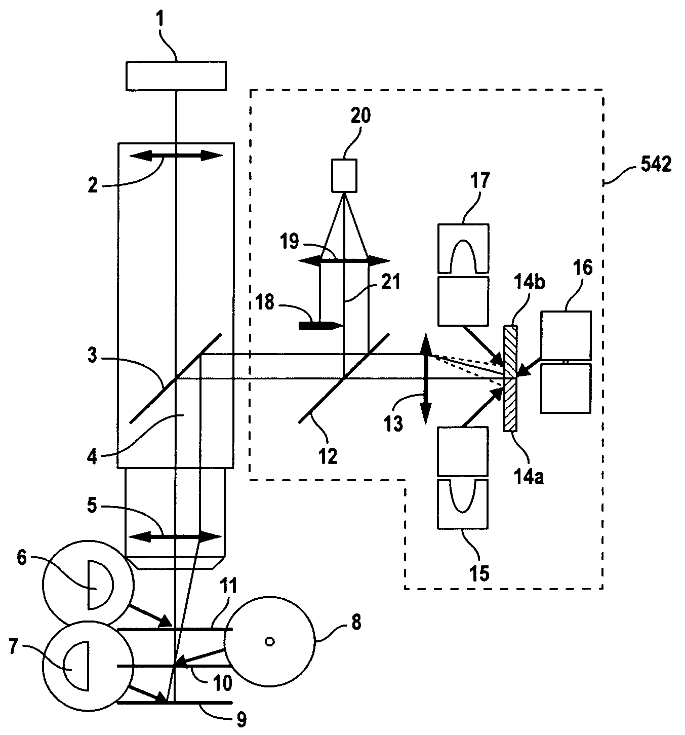
[0032]In accordance with one embodiment of the present invention, a substantially fixed distance is maintained between a control head and a target surface undergoing inspection and / or repair. To achieve this, a non-contacting sensor (alternatively referred to herein as gap sensor) continuously measures the distance between the control had and the target surface. A servo control system receives the measured distance, and in response, varies the position of the control head relative to the target surface so as to maintain the substantially fixed distance therebetween.

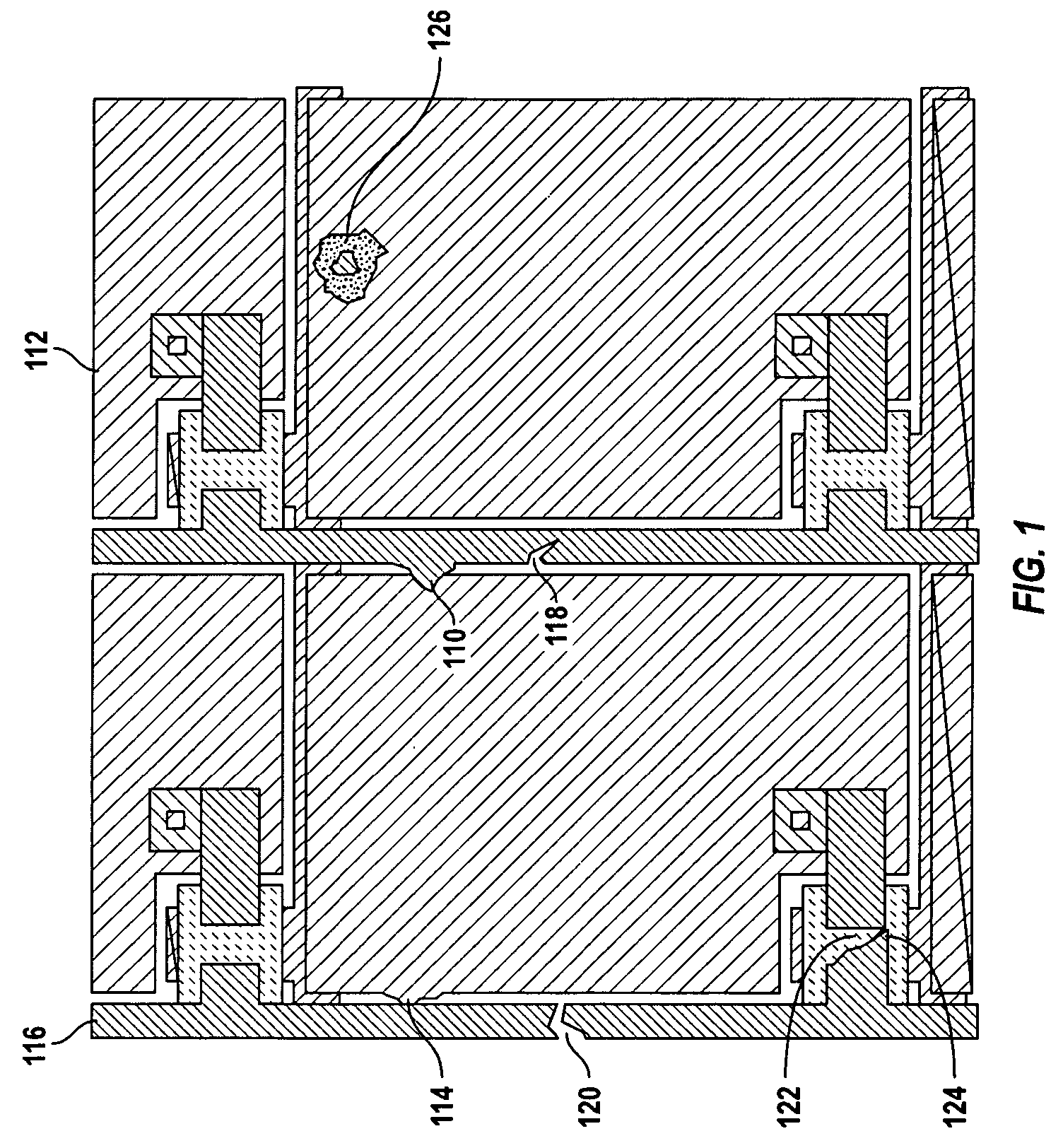
[0033]In one embodiment, the control head includes a microscope and / or a repair unit, and the target surface is a TFT array formed on a plate. In such embodiments, the microscope is continuously maintained in focus while being pointed at a TFT array, thereby eliminating the need to take time to re-focus at each site of interest across the TFT array plate. For such exemplary embodiments, it is desirable to maintain a subst...


PUM

PropertyMeasurementUnit
sizeaaaaaaaaaa
sizeaaaaaaaaaa
Depth of focusaaaaaaaaaa

Abstract

A tracking auto-focus system maintains a microscope pointed at a TFT array continuously in focus so as to eliminate the auto-focusing time that would otherwise be required. The tracking auto-focus system includes, in part, a microscope Z actuator, an auto-focus sensor, an analog-to-digital converter (ADC), a signal conditioner, a digital proportional integrating and differentiating (PID) controller, and a digital-to-analog converter. The actuator adjusts the distance between the microscope's objective lens and the target and includes, in part, an amplifier, a linear motor, and a linear encoder which provides positional feedback. The auto-focus sensor together with the ADC and signal conditioner continuously monitor and detect the distance between the microscope's objective lens and the target and supply the measured distance to the amplifier. The PID controller together with the DAC stabilizes the distance separating the microscope's objective lens and the target to maintain the best focus.

Description

CROSS-REFERENCES TO RELATED APPLICATIONS[0001]The present application claims priority under 35 U.S.C. 119(e) from application Ser. No. 60 / 646,119, filed Jan. 21, 2005 entitled “Tracking Auto Focus System”, the content of which is incorporated herein by reference in its entirety.BACKGROUND OF THE INVENTION[0002]The present invention relates to the flat panel displays based on liquid crystal (LC) technology, and more particularly to the inspection of components formed on such displays.[0003]During the manufacturing of LC displays, large clear plates of thin glass are used as a substrate for the deposition of thin film transistor (TFT) arrays. Usually, several independent TFT arrays are contained within one glass substrate plate and are often referred to as TFT panels.[0004]TFT pattern deposition is performed in a multitude of stages where in each stage, a particular material (such as a metal, indium tin oxide (ITO), crystalline silicon, amorphous silicon, etc.) is deposited on top of ...

Claims


Application Information

Patent Timeline
Patent Type & Authority Patents(United States)
IPC IPC(8): G01N21/00H01J3/14
CPCG02B7/282G02B21/245G02B7/285G02B21/0016G02B27/0955G02B27/40
Inventor WEISS, ADAM
Owner PHOTON DYNAMICS
Why Eureka
Try Eureka