Device for digital retinal imaging

a retinal imaging and digital technology, applied in the field of digital retinal imaging, can solve the problems of permanent vision loss in an area, none of the neural cells of the retina can yet be readily regenerated in the adult human, and human retina is susceptible to damage from a variety of causes, so as to achieve low power requirements, high contrast image, and simple operation.

Active Publication Date: 2008-02-19
INDIANA UNIV RES & TECH CORP
View PDF25 Cites 48 Cited by
  • Summary
  • Abstract
  • Description
  • Claims
  • Application Information

AI Technical Summary

Benefits of technology

[0015]The present invention relates to a device designed as an “eye sensor” for general use, achieving simplicity of operation, patient comfort, and low power requirements. The device is small, lightweight, and portable and presents a high contrast image. The device is suitable for providing triage for trauma and can readily interface with modern computer technology for remote or telemedicine applications. The device is able to operate in extreme heat or cold, when wet, while on a moving surface, and in a cordless mode. The device can be manufactured relatively inexpensively at significantly less cost than conventional scanning laser ophthalmoscopes.
[0018]The device is minimized in weight or mass and is portable, so that it is suitable for use outside of specialized ophthalmological offices and laboratories. Moving parts are eliminated or minimized, particularly those that require power to operate. The device can operate solely on batteries. The device can be motorized for remote access, using either DC operation or AC operation, as power supplies permit. The device can be made to draw its power though a single cable, such as to a computer. The computer can be a laptop, which is consistent with use as a portable device.

Problems solved by technology

The human retina is susceptible to damage from a variety of environmental factors, including laser light impact and other trauma, as well as disease.
In fact, none of the neural cells of the retina can yet be made to readily regrow in the adult human.
When damage is severe enough, there is permanent vision loss in an area.
If the affected region is in the central macula, known as the fovea, then the ability to see fine detail, read at rapid rates, or recognize objects at great distances may be lost.
The peripheral areas of vision do not have sufficient sampling density to perform these tasks to the same degree.
One of the chief problems in early detection has been the difficulty of imaging damage to a small area of retina.
Flood illumination produces images of the retina that often are subject to poor contrast due to the long range scatter not only from out of plane tissues, but also from the biological tissues that are inherently scattering, especially those within and near the retina.
No modestly priced, simple to use instrument is available that operates using this method.
A scanning laser ophthalmoscope is a large, expensive piece of equipment intended for use by ophthalmologists or other eye specialists in their offices or laboratories.
Equipment of this nature is not suitable for use by non-specialists or emergency personnel in the field.
This presents a problem with weight, footprint, and power.
Further, the video standards differ from country to country, so that video rate imaging has been made more difficult and cumbersome by requiring two sets of circuitry.
Both direct and indirect ophthalmoscopes require considerable skill to obtain a view of the macula of each eye, often not possessed by medical personnel not trained in an eye subspecialty.
Direct and indirect ophthalmoscopes do not produce images that can be stored and examined at another time or location.
Fundus camera devices do provide film or digital storage of the area examined; however, fundus camera devices using flood illumination of a wide area of the retina often fail to produce images of high contrast.
Untrained personnel often do not produce high quality results.
Non-mydriatic fundus cameras, requiring little or no dilation, depend upon flashed illumination and relatively expensive, high sensitivity detector arrays to obtain an image.
The data are often stored in proprietary file formats or require image storage, processing, or transmission methods that require additional software, which may not be compatible with other patient data.
Current imaging devices are not readily suited for use with personal digital assistants, wireless transmission, or the ubiquitous storage devices used with consumer digital cameras.
Such images, when using proprietary software or file formats, are not readily transferred and used with laptop or other computers in a shared environment.

Method used


Image

  • Device for digital retinal imaging
  • Device for digital retinal imaging
  • Device for digital retinal imaging

Examples


Embodiment Construction

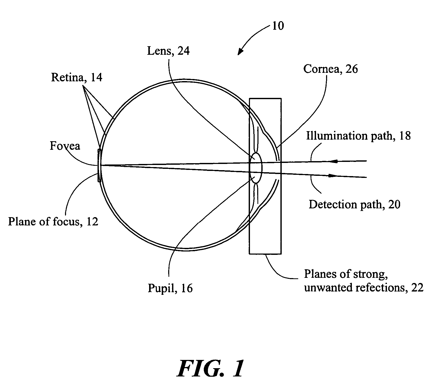
[0029]The present invention relates to a small, portable lightweight instrument or device of low cost particularly suitable for examining the retinal and subretinal layers of the eye 10 (see FIG. 1) for abnormalities. The device is noncontact and does not require drops to dilate the pupil of the eye. Referring to FIG. 1, the plane of focus 12 of the device for the retina 14 is that with the greatest amount of light return. When a human retina is imaged, light from an illumination source is passed through a slit to produce a line source and scanned across a desired focal plane in the eye after passing through the entrance pupil 16 of the eye, which is narrower than the focal plane of interest. Light enters through one or more portions of the pupil (see exemplary illumination path 18) and is remitted and collected through primarily other portions (see exemplary detection path 20), which minimizes the collection of unwanted light that is reflected from other planes 22, such as the lens...


PUM


Abstract

A portable, lightweight digital imaging device uses a slit scanning arrangement to obtain an image of the eye, in particular the retina. The scanning arrangement reduces the amount of target area illuminated at a time, thereby reducing the amount of unwanted light scatter and providing a higher contrast image. A detection arrangement receives the light remitted from the retinal plane and produces an image. The device is operable under battery power and ambient light conditions, such as outdoor or room lighting. The device is noncontact and does not require that the pupil of the eye be dilated with drops. The device can be used by personnel who do not have specialized training in the eye, such as emergency personnel, pediatricians, or general practitioners. Images can be viewed in the device or transmitted to a remote location. The device can also be used to provide images of the anterior segment of the eye or other small structures.

Description

CROSS REFERENCE TO RELATED APPLICATIONS[0001]This application claims priority under 35 U.S.C. 119(e) of U.S. Provisional Application No. 60 / 350,836, filed on Jan. 22, 2002, and U.S. Provisional Application No. 60 / 329,731, filed on Oct. 16, 2001, the disclosures of both of which are incorporated by reference herein.STATEMENT REGARDING FEDERALLY SPONSORED RESEARCH OR DEVELOPMENT[0002]The work leading to the invention received support from the United States federal government under Department of Defense Low Vision Grant No. DAMD-17-01-2-0032. The federal government may have certain rights in this invention.BACKGROUND OF THE INVENTION[0003]The human retina is susceptible to damage from a variety of environmental factors, including laser light impact and other trauma, as well as disease. Once damaged, the cells responsible for capturing light energy and transducing it into a neural signal, the photoreceptors, do not regenerate. In fact, none of the neural cells of the retina can yet be m...

Claims


Application Information

Patent Timeline
Patent Type & Authority Patents(United States)
IPC IPC(8): A61B3/14A61B3/10A61B3/12A61B3/15
CPCA61B3/156A61B3/1025
Inventor ELSNER, ANN E.
Owner INDIANA UNIV RES & TECH CORP
Why Eureka
Try Eureka