Optical scanning apparatus, illuminant apparatus and image forming apparatus

a technology of optical scanning and illumination, applied in the field of optical scanning apparatus, can solve the problems of limited improvement in recording speed, difficult to increase the number of illuminant channels in fabrication, and difficult to eliminate influences on thermal/electronic crosstalk and realize a short wavelength with respect to the semiconductor laser array

Inactive Publication Date: 2008-02-19
RICOH KK
View PDF19 Cites 38 Cited by
  • Summary
  • Abstract
  • Description
  • Claims
  • Application Information

AI Technical Summary

Benefits of technology

[0024]A more specific object of the present invention is to provide an optical scanning apparatus for scanning a surface to be scanned in the main scanning direction by simultaneously using a plurality of optical beams emitted from an illuminant wherein the optical scanning apparatus can correct misalignment of the beam pitch of beam spots on the scanned surface caused by environmental variations and time passage.
[0121]According to the above-mentioned inventions, it is possible to obtain a high-quality image by coinciding positions of the beam spots in a connection area between every two of the image stations.

Problems solved by technology

However, this approach has limited improvement with respect to the recording speed if motor durability, motor noise, motor vibration, laser modulation speed and the like are taken into account.
Regarding such a semiconductor laser array, however, it is extremely difficult to increase the number of the illuminant channels in course of fabrication thereof.
In addition, it is hard to eliminate influences on thermal / electronic crosstalk and realize a short wavelength with respect to the semiconductor laser array.
For these reasons, the semiconductor array is currently considered to be expensive as an illuminant part of an optical scanning apparatus.
However, when such a beam synthesizing part is used to synthesize a plurality of laser beams, a single-beam semiconductor laser has some problems in comparison with a semiconductor laser array in that environmental variations and time passage make alignment of beam spots on a surface to be scanned, for instance, the beam pitch and the scanning line interval, unstable.
In the case where such a mechanical system is used to adjust the light path, however, since the number of parts thereof inevitably increases, the part increase not only undermines reliability and duration of the whole system but also increases the system size.
In addition, there is a probability that hysteresis caused by backlash and others, vibration, noise and heat arise.
However, since a high driving voltage is required to implement these methods, an apparatus thereof becomes complicated and includes risk of heat generation.
Thus, these methods are considered to be impractical.
However, the intermediate transfer reference signal and the line synchronization signal are not synchronized with each other in the color image forming apparatus.
When the difference between the image writing start positions becomes large with respect to the subscanning direction, there arises color smear (misalignment of the individual toner images) and the resulting color image deteriorates.
However, even if this method is applied to color image forming apparatuses, there still is a probability that at most one line of misalignment arises with respect to the image writing start positions.
If the deflection direction of the light path does not coincide with the polarization plane of the optical beam, it is impossible to effectively deflect the light path by means of the liquid crystal element.

Method used


Image

  • Optical scanning apparatus, illuminant apparatus and image forming apparatus
  • Optical scanning apparatus, illuminant apparatus and image forming apparatus
  • Optical scanning apparatus, illuminant apparatus and image forming apparatus

Examples


first embodiment

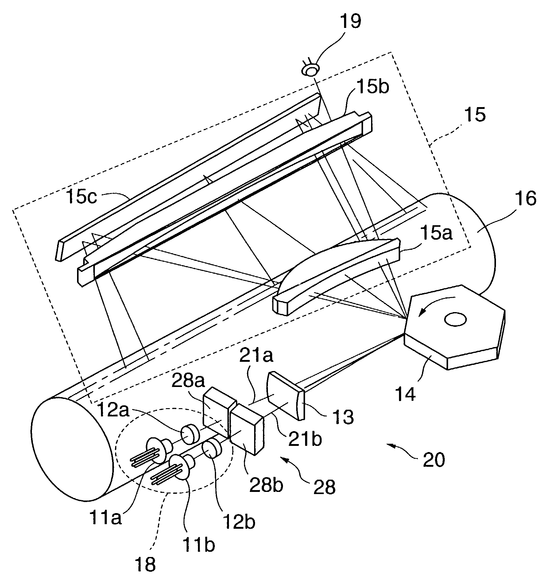
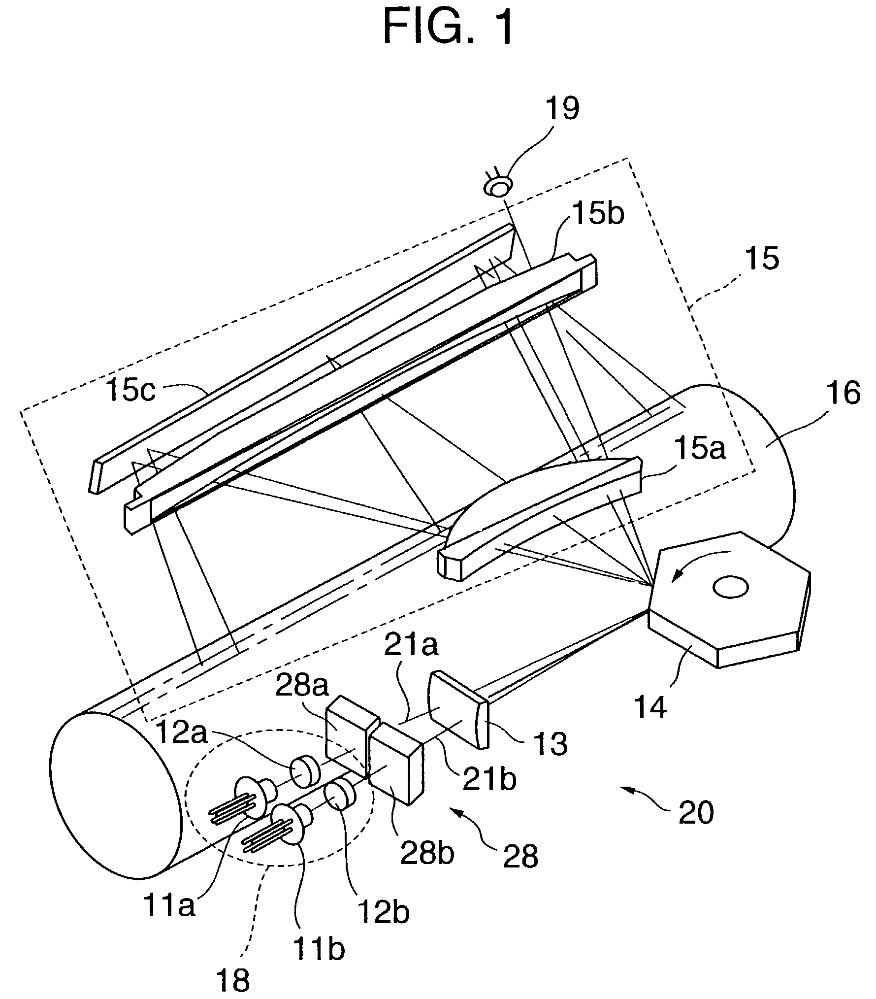
[0182]FIG. 1 is a perspective view of an optical scanning apparatus according to the

[0183]In FIG. 1, an illuminant apparatus 18 comprises at least two pairs of a semiconductor laser 11a and a coupling lens 12a and a semiconductor laser 11b and a coupling lens 12b. However, the illuminant apparatus 18 is not limited to this configuration. Also, the semiconductor lasers 11a and 11b may be single beam semiconductor lasers each of which has a single illuminant point or may be multi-beam semiconductor lasers (semiconductor laser arrays) each of which has a plurality of illuminant points.

[0184]The semiconductor lasers 11a and 11b emit laser light. The coupling lenses 12a and 12b couple the emitted laser light, and the coupled laser light results in two resulting optical beams (laser beams) 21a and 21b.

[0185]The optical beams 21a and 21b are shaped into the linear form by a cylindrical lens 13, and the linear optical beams are projected on a deflecting reflection surface of a polygon mirr...

fourth embodiment

[0387]FIG. 39 is a perspective view of an optical scanning apparatus according to the Here, the optical scanning apparatus is formed of a 2-beam scanning apparatus for scanning a surface to be scanned by simultaneously using two optical beams. However, the optical scanning apparatus may be formed of a multi-beam scanning apparatus using more than 2 beams.

[0388]Two semiconductor lasers 11a and 11b emit laser light. Two coupling lenses 112a and 112b couple the emitted laser light, and the coupled laser light results in two optical beams 121a and 121b. The optical beams 121a and 121b are shaped into a linear form by a cylindrical lens 113, and the linear optical beam is projected on a deflecting reflection surface of a polygon mirror 114, which serves as a deflector, in order to produce an optical beam that is focused on-the subscanning direction and is linearly formed with respect to the main scanning direction. Then, the deflected linear optical beam is projected to an optical scann...


PUM


Abstract

An optical scanning apparatus scans a surface to be scanned in a main scanning direction by simultaneously using a plurality of optical spots formed of a plurality of optical beams emitted from an illuminant, comprising: a light path deflecting part deflecting a light path of at least one of the optical beams, wherein the light path deflecting part is provided in light paths of the optical beams wherein the light path deflecting part may use a liquid crystal deflecting element formed of a liquid crystal element being controllable by an electronic signal to deflect the light path of the one of the optical beams.

Description

BACKGROUND OF THE INVENTION[0001]1. Field of the Invention[0002]The present invention generally relates to an optical scanning apparatus (multi-beam scanning apparatus) for using a plurality of optical beams projected from an illuminant to simultaneously scan a surface to be scanned in the main scanning direction, an illuminant apparatus prepared for the optical scanning apparatus, and an image forming apparatus that uses the optical scanning apparatus as an optical writing system such as a laser color printer, a digital color copier, a laser plotter and a laser facsimile.[0003]2. Description of the Related Art[0004]In order to improve the recording speed of an optical scanning apparatus that is used as an optical writing system in an image forming apparatus, there is an approach in which the rotational speed of a polygon mirror, which serves as a deflecting part, is increased. However, this approach has limited improvement with respect to the recording speed if motor durability, mo...

Claims


Application Information

Patent Timeline
Patent Type & Authority Patents(United States)
IPC IPC(8): G02B26/08G02B26/12H04N1/113
CPCG02B26/123B41J2/473H04N1/1135
Inventor AMADA, TAKUSUZUKI, SEIZOITOH, SATORUNAKAJIMA, TOMOHIRO
Owner RICOH KK
Why Eureka
Try Eureka