Semiconductor device and method for manufacturing the same

a technology of semiconductors and semiconductors, applied in the direction of radiation controlled devices, transistors, basic electric elements, etc., can solve the problems of weak mounting strength, difficult to see the connection portion of an optical sensor electrode and an electrode terminal, and the inability to form a connection terminal on the side face of a substrate, etc., to achieve the effect of increasing the area for connecting with the wiring board, increasing the mounting strength, and confirming the condition of the connection

Inactive Publication Date: 2008-02-26
SEMICON ENERGY LAB CO LTD
View PDF20 Cites 68 Cited by
  • Summary
  • Abstract
  • Description
  • Claims
  • Application Information

AI Technical Summary

Benefits of technology

[0014]In view of the above described problems, it is an object of the present invention to provide a semiconductor device formed over an insulating substrate, typically an optical sensor, a solar battery, or a circuit using a TFT, a semiconductor device having a structure in which mounting strength to a wiring board can be increased and which can make it mount on a wiring board with high density, and further provide a method for manufacturing the same.
[0030]The semiconductor device of the present invention has a concave portion in a side face of an insulating substrate, and a connection terminal can be formed in the portion. In other words, a semiconductor device having a side electrode can be formed. Thus, an area for connection with a wiring board can be increased, the mounting strength is also increased, and at the same time, the condition of connection can be seen and confirmed visibly. Accordingly, reliability on process can be enhanced. Also, since a connection terminal can be formed by forming an opening portion in the substrate and forming a conductive film along the opening portion, connection terminals for a plurality of semiconductor device can be provided on one substrate. Therefore, it is possible to form a plurality of semiconductors device by using one substrate, to increase throughput in the step of forming a connection terminal, and to mass-produce. Moreover, a semiconductor element is formed over a substrate, and the area of the substrate and the area of an effective region needed for functioning as the semiconductor element are almost equal. Thus, a large number of semiconductor elements can be integrated highly on a wiring board or the like. These and other objects, features and advantages of the present invention become more apparent upon reading of the following detailed description along with the accompanying drawings.

Problems solved by technology

Therefore, in the case of sensing white fluorescent light that hardly include a spectrum of the infrared region and sunlight having a wide spectrum from the ultraviolet region to the infrared region, there is a problem that sensing results of each light are different while actual illuminance thereof are equal.
However, since a plastic substrate is thin, a connection terminal cannot be formed on a side face of a substrate.
Thus, there is a problem that mounting strength is weak as compared with a side electrode structure since the bonding area is small.
In addition, it is difficult to see a connection portion of an electrode of the optical sensor and an electrode terminal and to judge whether these connects to each other surely, because a region where the wiring board is connected to the optical sensor is in the lower part of a substrate of the optical sensor.
In addition, since some conventional organic resin materials or plastic substrates have poor heat-resistance, they cannot be mounted on a wiring board by a reflow step using solders.
Accordingly, such a packaging structure of an optical sensor is interfering with high integration on a wiring board.

Method used


Image

  • Semiconductor device and method for manufacturing the same
  • Semiconductor device and method for manufacturing the same
  • Semiconductor device and method for manufacturing the same

Examples


embodiment mode 1

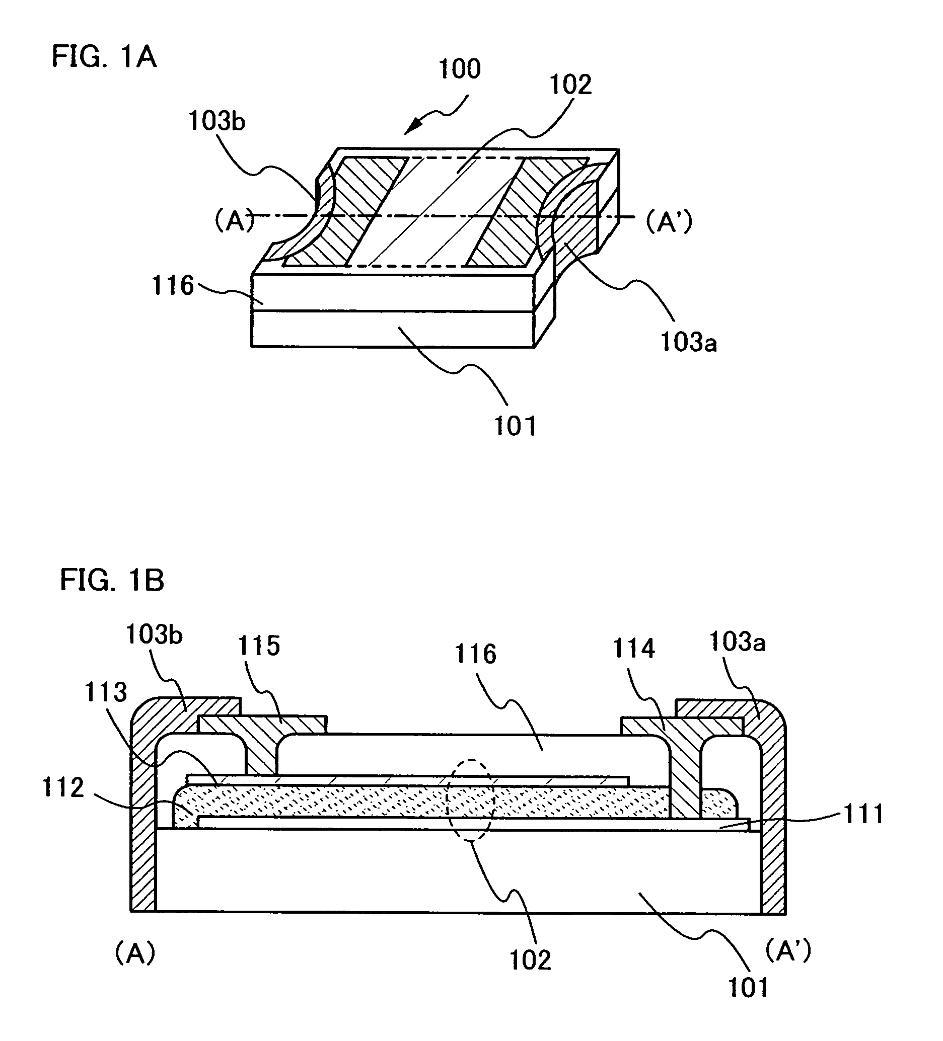
[0044]An optical sensor that is formed over a plastic substrate and that has a concave portion in a side face thereof is described with reference to FIGS. 1A and 1B in this embodiment mode.

[0045]FIG. 1A is an oblique drawing of an optical sensor 100 of the present invention. A semiconductor element 102 is formed over a plastic substrate 101. A side face of the optical sensor 100 has a concave shape, and a conductive film to be connection terminals 103a and 103b is formed in this area.

[0046]The semiconductor element 102 can be integrally formed on the substrate by using a semiconductor film, preferably, a semiconductor thin film, and thus, downsizing and thinning of a semiconductor device can be achieved.

[0047]The concave shape in the side face of the optical sensor is curved in this embodiment mode. Note that the concave shape may have a flat surface. That is to say, the concave shape is a semi cylindrical having a curved surface or a rectangular column having a flat surface.

[0048]F...

embodiment mode 2

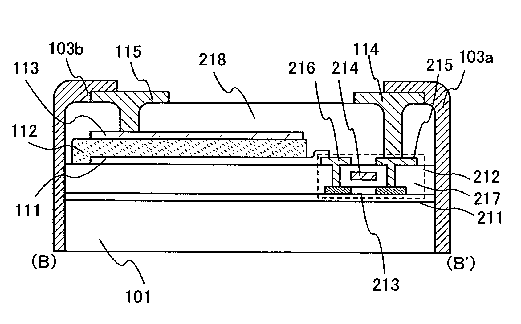
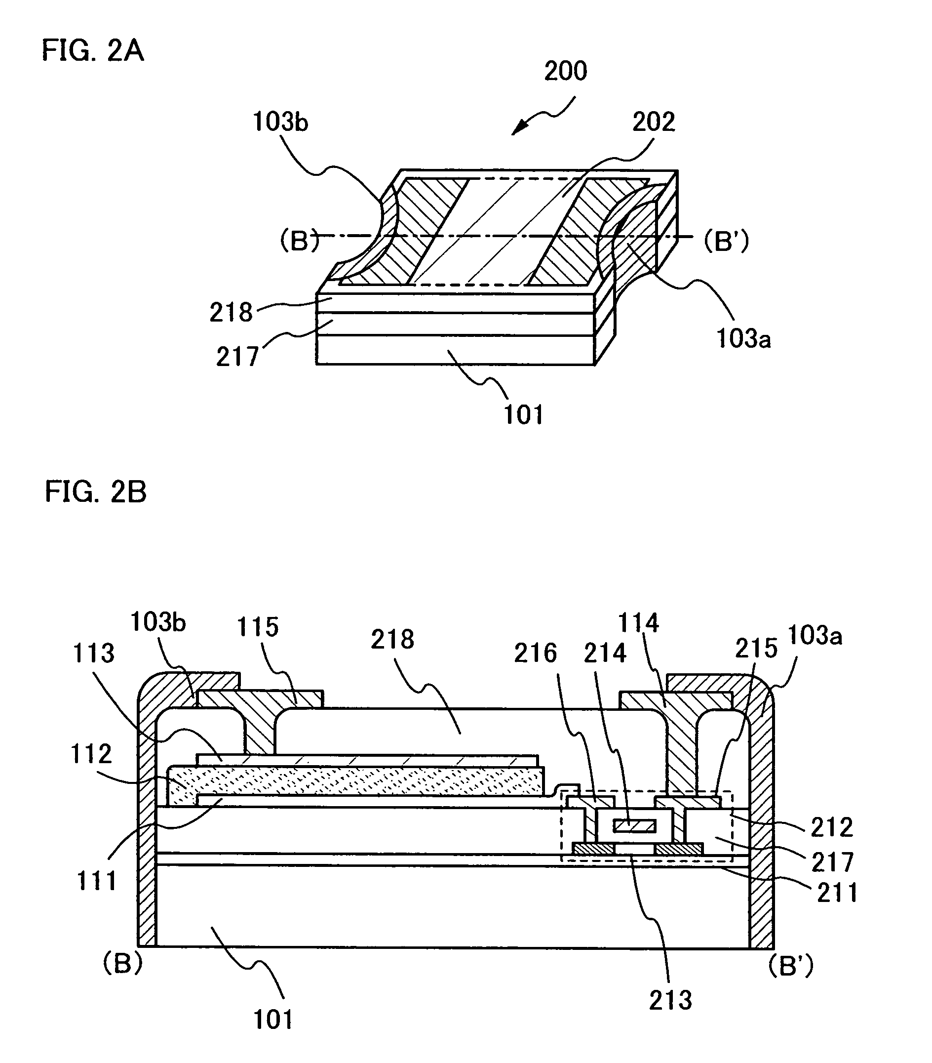
[0064]An optical sensor having a circuit for amplifying current detected in a light-receiving portion is described with reference to FIGS. 2A and 2B. An example of using a thin film transistor (hereinafter, referred to as a TFT) as an element constituting an amplifier circuit is shown, but the present invention is not limited thereto and can employ an operational amplifier (op-amp) and the like.

[0065]FIG. 2A is an oblique drawing of an optical sensor of this embodiment mode. As in Embodiment Mode 1, a semiconductor element 202 is formed on a surface of a plastic substrate 101. A diode or a TFT having such a structure shown in Embodiment Mode 1 can be appropriately applied to the semiconductor element. In addition, a side face of an optical sensor 200 has a concave portion, and a conductive film to be connection terminals 103a and 103b is formed therein. The shape shown in Embodiment Mode 1 can be applied to the shape of the concave portion in the side face of the optical sensor.

[006...

embodiment mode 3

[0078]An example of a driver circuit of an optical sensor in Embodiment Mode 2 is shown with reference to FIG. 3. In this embodiment mode, a current mirror circuit is used as an amplifier circuit in the optical sensor.

[0079]Herein, two transistors are connected to each other and one of them is connected to a diode (a light-receiving portion). The TFT connected to a diode 301 is a first TFT 302, and the TFT that is connected to the first TFT in parallel is a second TFT 303. Gate electrodes and source wirings of the first TFT 302 and the second TFT 303 are connected to one another. A drain of the first TFT 302 is connected to a cathode of the diode 301, and an anode of the diode 301 is connected to a drain of the second TFT 303. Sources of the first TFT and the second TFT are connected to VSS 304. The anode of the diode and the drain of the second TFT are connected to VDD 305 that is an output terminal, and brightness of light can be detected by a value of current flowing at the point...


PUM


Abstract

The present invention provides a semiconductor device formed over an insulating substrate, typically a semiconductor device having a structure in which mounting strength to a wiring board can be increased in an optical sensor, a solar battery, or a circuit using a TFT, and which can make it mount on a wiring board with high density, and further a method for manufacturing the same. According to the present invention, in a semiconductor device, a semiconductor element is formed on an insulating substrate, a concave portion is formed on a side face of the semiconductor device, and a conductive film electrically connected to the semiconductor element is formed in the concave portion.

Description

BACKGROUND OF THE INVENTION[0001]1. Field of the Invention[0002]The present invention relates to a semiconductor device that is thin and lightweight, and a method for manufacturing the same.[0003]2. Description of the Related Art[0004]In recent yeas, cellular phones spread with progress of communication technology. Furthermore, more moving images and more information are greatly expected to be sent in the future. On the other hand, personal computers for mobile are produced by virtue of the weight saving. A large number of portable information terminal such as PDA (personal digital assistants), which begin from an electronic notebook, are produced, and are being widely used. Moreover, most of such portable information devices are each equipped with a flat panel display with the development in display devices.[0005]In such a display device, brightness in the periphery of the display device is detected, and its display brightness is adjusted. Thus, needless electric power consumption...

Claims


Application Information

Patent Timeline
Patent Type & Authority Patents(United States)
IPC IPC(8): H01L27/01H01L23/538H01L21/00H01L23/00H01L27/06H01L27/12H01L27/14H01L27/144H01L27/146H01L29/78H01L29/786H01L29/792H01L29/861H01L31/00H01L31/02H01L31/0203H01L31/0392H01L31/048H01L31/18
CPCH01L27/1446H01L27/14618H01L31/0203H01L31/048H01L2924/0002Y02E10/50H01L2924/00H01L21/02225H01L21/048H01L21/4763H01L21/76205H01L27/146H01L29/786
Inventor NISHI, KAZUOADACHI, HIROKIMARUYAMA, JUNYAKUSUMOTO, NAOTOSUGAWARA, YUUSUKEAOKI, TOMOYUKISUGIYAMA, EIJITAKAHASHI, HIRONOBU
Owner SEMICON ENERGY LAB CO LTD
Why Eureka
Try Eureka