
Integrated method for restoring electrical power cable

a technology of electrical power cable and integrated method, which is applied in the direction of cable fittings in the presence of gas/oil, apparatus for repairing insulation/armour cables, line/current collector details, etc. it can solve the problems of not reaching the original anticipated longevity of 30 to 40 years, still having practical limitations when reclaiming underground residential distribution cables, and suffering premature breakdown. , to achieve the effect of improving efficiency, facilitating the rapid replacement of connectors, and improving overall efficiency

Active Publication Date: 2008-04-08
NOVINIUM LLC
View PDF25 Cites 45 Cited by
  • Summary
  • Abstract
  • Description
  • Claims
  • Application Information

AI Technical Summary

Benefits of technology

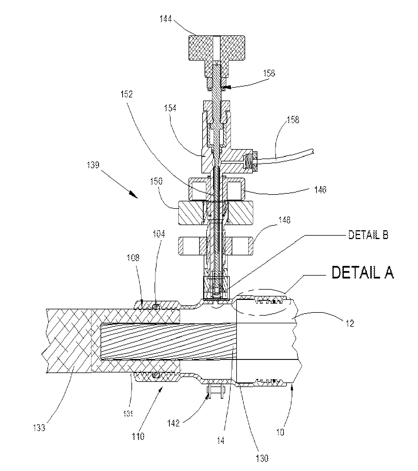
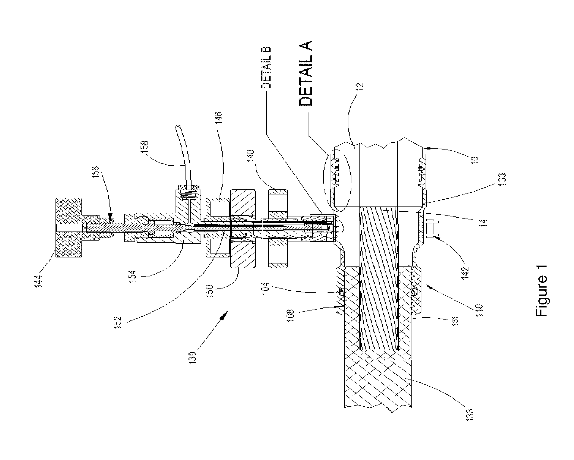
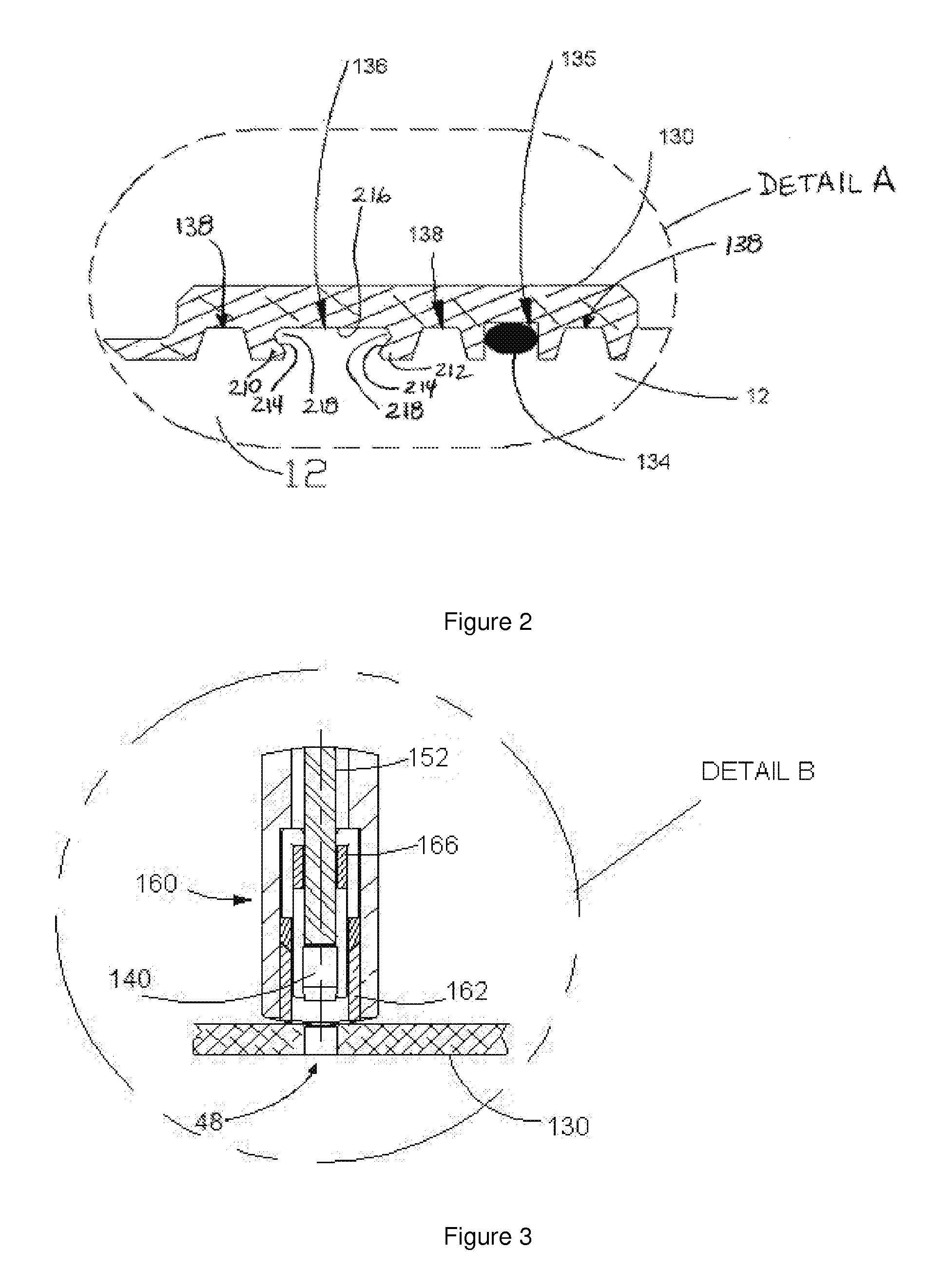
[0033]It has now been discovered that an improved overall efficiency can be enjoyed in treating the above-described stranded-conductor cables having inadequate interstitial volume relative to the amount of dielectric enhancement fluid required, particularly URD cables. This improved efficiency is realized when the existing splices and terminations of at least one in-service cable section (i.e., a cable segment or sub-segment) are replaced with corresponding high-pressure connectors of the type described below and the cable section is injected with a dielectric enhancement fluid which is confined within the interstitial void volume at an elevated pressure. Site-available vacuum excavation equipment facilitates the expeditious replacement of the connectors. With the instant integrated method, it is now possible to assess, and completely treat, such an in-service cable section using only a single switching cycle, preferably in a single visit to the site of the cable section.

Problems solved by technology

Unfortunately, these cables (which generally comprise a stranded (or solid) conductor surrounded by a semi-conducting conductor shield, a polymeric insulation jacket, and an insulation shield), particularly those installed prior to 1985, often suffer premature breakdown and do not attain their originally anticipated longevity of 30 to 40 years.
This method and variations thereof employing certain rapidly diffusing components (U.S. Pat. Nos. 5,372,840 and 5,372,841) have enjoyed commercial success over the last decade or so, but they still have some practical limitations when reclaiming underground residential distribution (URD) cables.
The latter have a relatively small diameter (typically smaller than 4 / 0 and a conductor area of 2) and therefore present insufficient interstitial volume relative to the amount of retardant fluid required for optimum dielectric performance (e.g., sufficient retardant to saturate the conductor shield and insulation of the cable segment).
This problem, however, is not limited to cables having such relatively small conductors since other geometric factors, such as strand compression and the greater insulation thickness associated with higher voltage cables, can also lead to insufficient interstitial volume in larger cables.
Further, not using vacuum results in residual bubbles in splices or other discontinuities along the flow path.
Bubbles, of course, lead to regions of under-treatment, a huge issue when one considers that this low pressure approach typically under treats URD cables even under the best of circumstances.(g) Inject desiccant (e.g., an anhydrous alcohol such as isopropyl alcohol or a mixture of anhydrous alcohols and alkoxy-functional silanes) into the interstitial void volume.
Finally, the desiccant mitigates premature reaction of water with the treatment fluid, which would increase the bulk viscosity of the latter and impair efficient flow through the interstices.(h) Inject tree retardant fluid using a pressure of less than 30 psig (pounds per square inch gage), leaving the cable unattended until the interstitial void volume is filled (several hours, and more typically, several days).
Those skilled in the art will readily appreciate that it is not practical to de-energize a given cable segment each time it is visited since the switching process is time consuming (and thus expensive) and, when circuits are not in a loop configuration, the electrical end-user cannot be bothered with repeated outages.
Ironically, these cables are even more expensive to deal with than if they had been simply replaced to begin with because they were visited by an injection crew first and the labor expense is ultimately absorbed by the circuit owner.
Moreover, the repetitive trips to an injection site are not only costly in terms of human resource, but each exposure of workers to energized equipment presents additional risk of serious injury or fatality and it is clearly beneficial to minimize such interactions.

Method used


Image

  • Integrated method for restoring electrical power cable
  • Integrated method for restoring electrical power cable
  • Integrated method for restoring electrical power cable

Examples


Embodiment Construction

[0044]For the purposes herein, the in-service electrical cable according to the present integrated method is generally of the type used in underground residential distribution and typically comprises a central core of a stranded copper or aluminum conductor encased in polymeric insulation jacket. As is well known in the art, there is usually also a semi-conducting or high permittivity polymeric conductor shield positioned between the conductor and the insulation jacket. Further, there is often a semi-conducting insulation shield covering the insulation, the latter being ordinarily wrapped with a wire or metal foil grounding strip and, optionally, encased in an outer polymeric protective jacket. The above-mentioned interstitial volume is the void space within the conductor shield, and is defined by the strand geometry. The insulation is preferably a polyolefin polymer, such as polyethylene or a copolymer of ethylene and propylene or vinyl acetate or is a solid-fluid dielectric such a...


PUM

PropertyMeasurementUnit
Temperatureaaaaaaaaaa
Timeaaaaaaaaaa
Percent by massaaaaaaaaaa

Abstract

A method for extending the useful life of an in-service electrical cable section having at least two existing connectors attached thereto and a conductor surrounded by a conductor shield encased in a polymeric insulation jacket with an interstitial void volume in the region of the conductor. The method includes replacing each connector with a corresponding high-pressure connector, and injecting a dielectric enhancement fluid into the void volume and confining the fluid therein at a pressure sufficient to introduce at least about 0.75Q of the fluid. Wherein Q represents the weight of the fluid which would saturate the conductor shield and insulation jacket, and the void volume at atmospheric pressure being less than that which would accommodate the amount 0.75Q. The method is carried out using only a single switching cycle.

Description

CROSS REFERENCE TO RELATED APPLICATION[0001]This application claims priority benefit of provisional application Ser. No. 60 / 712,644 filed Aug. 30, 2005.FIELD OF THE INVENTION[0002]The present invention relates to a method for extending the longevity of an electrical power cable. More particularly, the invention relates to an improved method for restoring the dielectric properties of an in-service electrical cable segment wherein a dielectric enhancing fluid is injected into the interstitial void volume of the cable.BACKGROUND OF THE INVENTION[0003]Extensive networks of underground electrical cables are in place in many parts of the industrialized world. Such underground distribution offers great advantage over conventional overhead lines in that it is not subject to wind, ice or lightning damage and is thus viewed as a reliable means for delivering electrical power without obstructing the surrounding landscape, the latter feature being particularly appreciated in suburban and urban ...

Claims


Application Information

Patent Timeline
IPC IPC(8): H01R43/00
CPCH02G1/16H02G15/26Y10T29/49176Y10T29/49178Y10T29/49174
Inventor BERTINI, GLEN J.
Owner NOVINIUM LLC
Learn More