Process to produce a commercial soil additive by extracting waste heat, exhaust gas, and other combustion by-products from a coal power generator

a technology of exhaust gas and coal power generator, which is applied in the direction of soil conditioning composition, application, energy input, etc., can solve the problems of difficult to use commercial horticultural and agricultural additives, and achieve the effect of maximum growth of bio-mass materials and low cos

Inactive Publication Date: 2008-07-01
LEE L COURTLAND
View PDF1 Cites 8 Cited by
  • Summary
  • Abstract
  • Description
  • Claims
  • Application Information

AI Technical Summary

Benefits of technology

[0007]The present invention takes advantage of the exhaust gas and by-products produced from a coal power generator to produce a large supply of a commercial soil additive, including an additive with a low pH, at a relatively low cost. Generally, the exhaust gas is directed into a growing cell to “grow out” a bio-mass material in a confined space. By adding and controlling various components and taking advantage of waste heat in the exhaust gas, maximum growth of the bio-mass material is achieved. The bio-mass material is harvested to provide the commercial soil additive that is then converted into compost and / or mulch using standard horticultural techniques. This process develops a win-win solution driven by both a needed alternative process for coal fired energy production and a commercially viable by-product soil additive to replenish depleted soil.
[0009]The present process not only burns a wide variety of coal cleanly, but the exhaust gas, including any combustion by-products, from a coal power generator can be inexpensively converted into a commercial soil additive used in mulch and / or compost mixing with other combustion by-products or additives to improve productivity of soil for agriculture or ornamental land use. The present invention eliminates the need for smokestacks for dissipation of exhaust gas from coal power generators resulting in siting advantages and an increase in the competitive advantage of coal for future power use. A commercial soil additive that is adjustable to several pH values is the end result of this process, which will both improve organic matter in soil and reduce carbon dioxide and other pollutants in the atmosphere.
[0010]The present invention is very versatile and may be operated in all seasons and in a wide variety of latitudes and climates using most coals. Exhaust gas contains emissions, such as carbon dioxide, nitrogen oxides, and sulfurs, which are converted into a commercial soil additive that is used in mulch and compost. This cleans the air and provides an economic method of recovering the carbon in coal in addition to conserving energy. The present invention adds value to coal resources by converting an existing liability into a saleable product. In general, the process is relatively low cost, improves coals political advantages, and enhances the potential of America's vast domestic coal resources. The commercial soil additive can supply a product that adjusts the pH of soil downward, which is currently difficult to do with available commercial horticultural and agricultural additives. The resulting commercial soil additive is a needed soil augmentation for organic rich mulch and compost that is useful for depleted soil. The commercial soil additive may be used to lower the pH of certain soils making it a premium product for alkaline soils, limestone soils, and desert soils. Using state of the art confined gas detection technologies, the present invention monitors control venting of cleaned stack gas. The process can automatically recycle the exhaust product in the growing cells until the emission levels in the exhaust product are acceptable to vent. Production of soil additives near a power plant can take advantage of back hauling in empty coal cars. Public acceptance of no smoke stack technology may allow small power plant construction near a city or suburb, close to the market for a commercial soil additive.

Problems solved by technology

The commercial soil additive can supply a product that adjusts the pH of soil downward, which is currently difficult to do with available commercial horticultural and agricultural additives.

Method used


Image

  • Process to produce a commercial soil additive by extracting waste heat, exhaust gas, and other combustion by-products from a coal power generator
  • Process to produce a commercial soil additive by extracting waste heat, exhaust gas, and other combustion by-products from a coal power generator
  • Process to produce a commercial soil additive by extracting waste heat, exhaust gas, and other combustion by-products from a coal power generator

Examples


example 1

Growing Cells 14

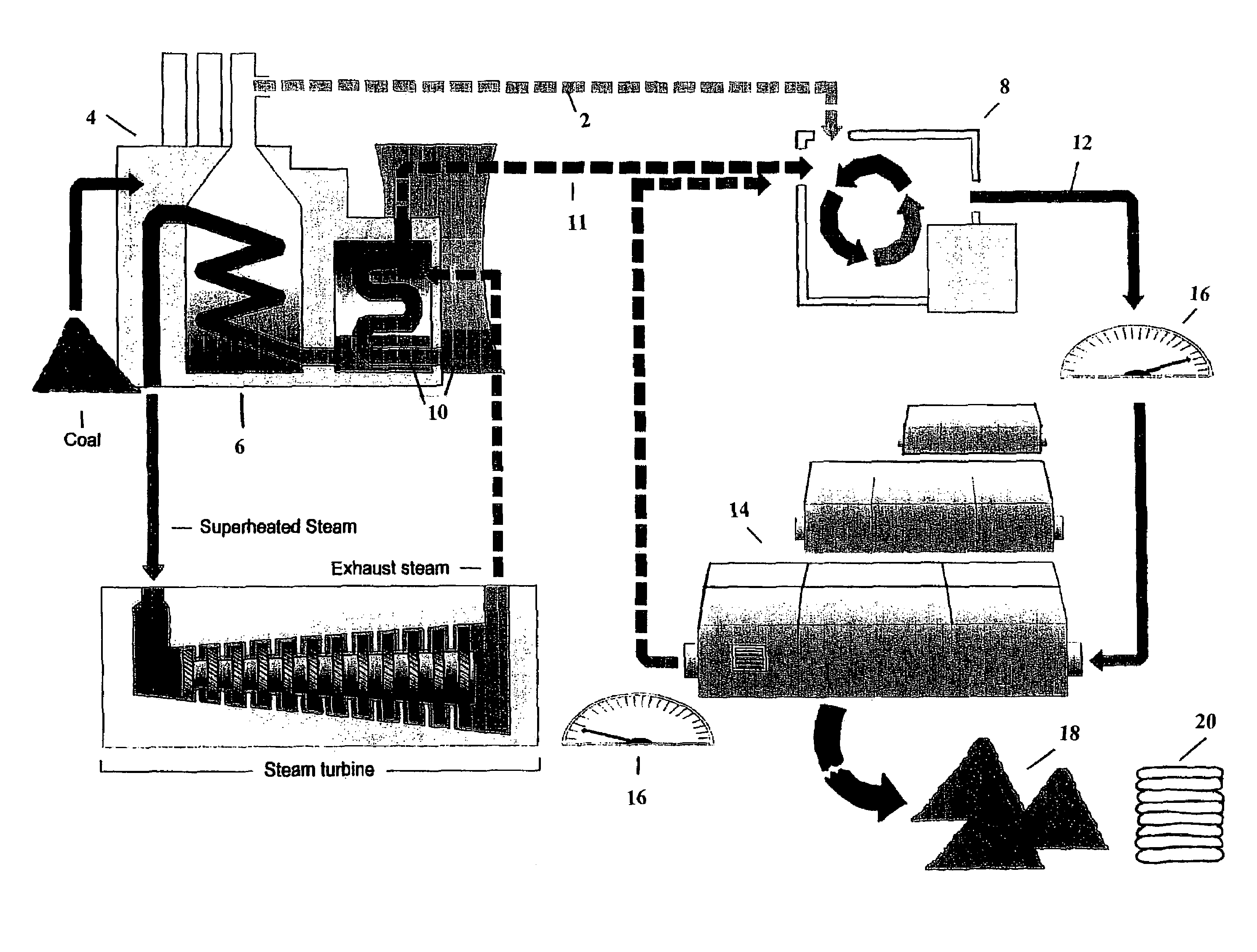
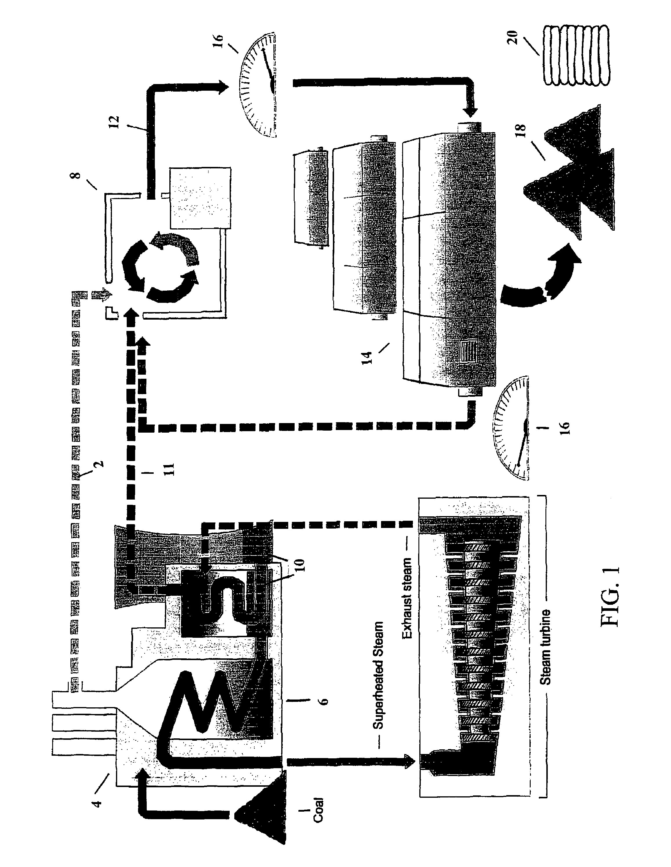
[0022]FIG. 1 shows a first preferred embodiment whereby the exhaust product 12, upon leaving the mixing chamber 8, is blown through a series of growing cells 14, preferably horticulture growing frames, tailored to available growing space, climate and other factors. In a preferred embodiment, a 50′×300′ horticulture hoop house with bottom heating cables, supplied from the waste heat of the mixing chamber 8, may be used. It is also preferred that the growing cells 14 have access for plant farming and harvesting. For example, in northern latitudes, apex hoops for snow loads would be recommended. Additionally, it is preferred that UV treated plastic be used because of its economical year round use. A base growing soil, preferably at least one foot above the heating cables, would be a recommended thickness for maximum growth. The number of frames is proportional to the amount of exhaust gas 12, allowing extra frames for removal of the bio-mass material, cleaning and repai...

example 2

Growing Cell Pond

[0030]As shown in FIG. 4, instead of blowing the exhaust product 12 into the air space of the growing cells 14, the exhaust product 12 is pumped into bubbling devices 302, preferably bubbling tubes, located within a growing cell pond 304, such as a closed growing pond. The bubbling devices 302 are preferably submerged about 6 feet below the water surface of the growing cell pond 304. The growing cell pond 304 may be located within a preferred commercial hoop structure 306. A pressure switch controls the pumping of the exhaust product 12 to maintain higher pressure than the bottom liquid pressure and bubbles the exhaust product 12 through water which is monitored for temperature, pH, and nutrient content by similar space gas detection units as previously mentioned. Fertilizer, lime, or other controlling material can be added directly to the water. A propeller or water jet is installed to retain circulation. Waste heat from the mixing chamber 8 can directly warm the w...

example 3

Deep Water Growing Cells

[0033]FIG. 5A and FIG. 5B show a preferred embodiment dealing with either pumping exhaust product 12 from a mixing chamber 8 or pumping nutrient rich water 222 from a pressurized water filled mixing chamber 208 directly into deep water growing cells 402, 404, 406 preferably up to 10 meters or more. When exhaust product 12 is pumped to the deep water growing cells 402, 404, 406 the exhaust product 12 is provided using bubbling devices 408. The dimensions of the deep water growing cell 402, 404, 406 depends on the area availability and the throughput of exhaust product 12. The deep water growing cells 402, 404, 406 may be open growing ponds, fresh water, or salt water growing cell. The deep water growing cells 402, 404, 406 can be separated by earthen dikes, wire nets with tyvec type fabric separation or even open net (nylon or poly) that encourages bio-mass material growth while limiting mixing between deep water growing cells 402, 404, 406. Bio-mass material ...


PUM

PropertyMeasurementUnit
thicknessaaaaaaaaaa
pHaaaaaaaaaa
areasaaaaaaaaaa

Abstract

Exhaust gas 2 from a coal power generator 4 may be used to provide a commercial soil additive. The exhaust gas 2 is fed to a growing cell 14 containing bio-mass material. After the bio-mass material matures, the bio-mass material is harvested to produce the commercial soil additive, which is preferably treated to produce mulch 18 and compost 20.

Description

CROSS-REFERENCE TO RELATED APPLICATIONS[0001]This application claims the benefit, under 35 U.S.C. 119(e), of U.S. Provisional Application No. 60 / 435,871 filed Dec. 24, 2002, the contents of which are incorporated herein by reference.BACKGROUND OF THE INVENTION[0002]1. Field of the Invention[0003]The present invention related to a process for producing a commercial soil additive from exhaust gas generated from a coal power generator.[0004]2. Description of Related Art[0005]Over a million new homes per year have been developed from American farm land in recent decades with little being done to improve the soil after development. Soil additives may be used to improve soil quality in these areas as well as broader agriculture applications. Currently, peat moss is used as a soil additive to lower pH. However, it is mostly imported from Canada and is very expensive for agricultural use. A greater supply of soil additives, particularly in a wider pH range, could be used to replenish deplet...

Claims


Application Information

Patent Timeline
Patent Type & Authority Patents(United States)
IPC IPC(8): C09K17/14C05C11/00C05F9/04C05F11/00
CPCC05C11/00C05F11/00C05F9/04Y10S71/903Y02P20/129Y02P20/145Y02A40/20
Inventor LEE, L. COURTLAND
Owner LEE L COURTLAND
Why Eureka
Try Eureka