

Glass-based SOI structures
a glass-based, soi technology, applied in the direction of semiconductor/solid-state device manufacturing, basic electric elements, electric apparatus, etc., can solve the problems of difficult replacement of silicon wafers with glass or glass-ceramic of the type, quartz itself is a relatively expensive material, and the cost of such structures has been the cost of silicon wafers, etc., to achieve strong bonding and higher pressur
- Summary
- Abstract
- Description
- Claims
- Application Information
AI Technical Summary
Benefits of technology
Problems solved by technology
Method used
Image

Examples
example 1
[0246]A 4-inch diameter phosphorus-doped silicon wafer (hereinafter referred to as the “silicon wafer”) having a thickness of 0.525 mm was implanted with hydrogen ions at 69 KeV at a concentration of 6×10¹⁶ ions / cm2 using commercially available, room temperature, ion implantation techniques. The phosphorus-doped silicon had a 0° C. CTE of 24×10−7 / ° C. and a 300° C. CTE of 38×10−7 / ° C. The wafer was obtained from SiliconSense Inc., Nashua, N.H., and, as reported by the manufacturer, had a resistivity of 1-10 ohm·cm. Boron-doped silicon wafers were also used in various of the examples with equivalent results to the phosphorus-doped wafers.
[0247]A 4-inch diameter glass wafer having a thickness of 1 mm was washed in detergent, rinsed in distilled water, soaked in 10% nitric acid for 1 hour, and finally rinsed again in distilled water. It was then placed in a clean room hood and allowed to dry.
[0248]The glass wafer was made of CORNING INCORPORATED GLASS COMPOSITION NO. 7070. On a weight ...
example 2
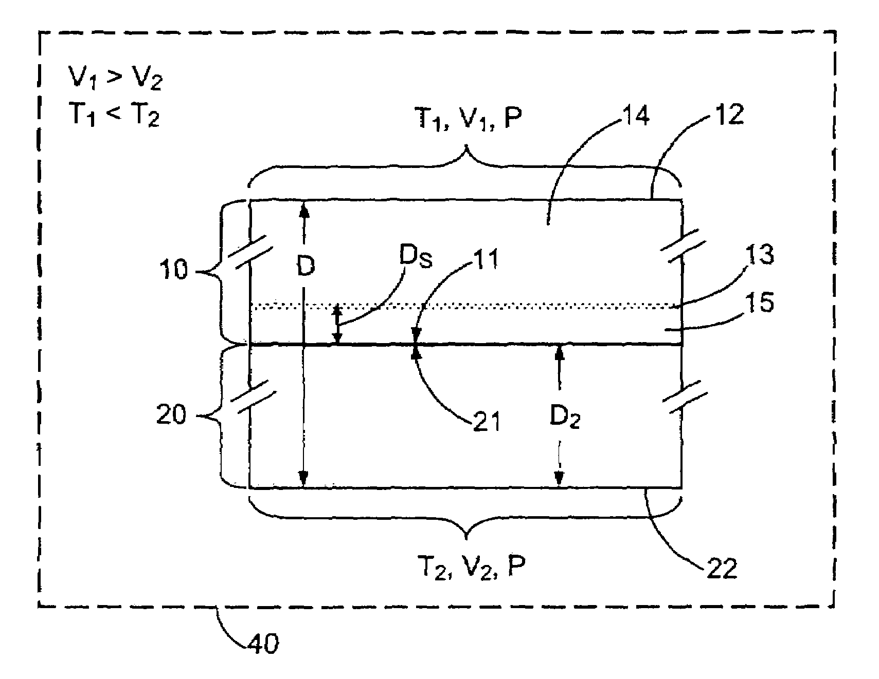
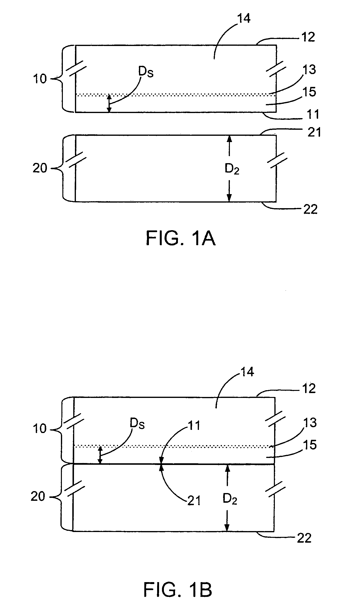
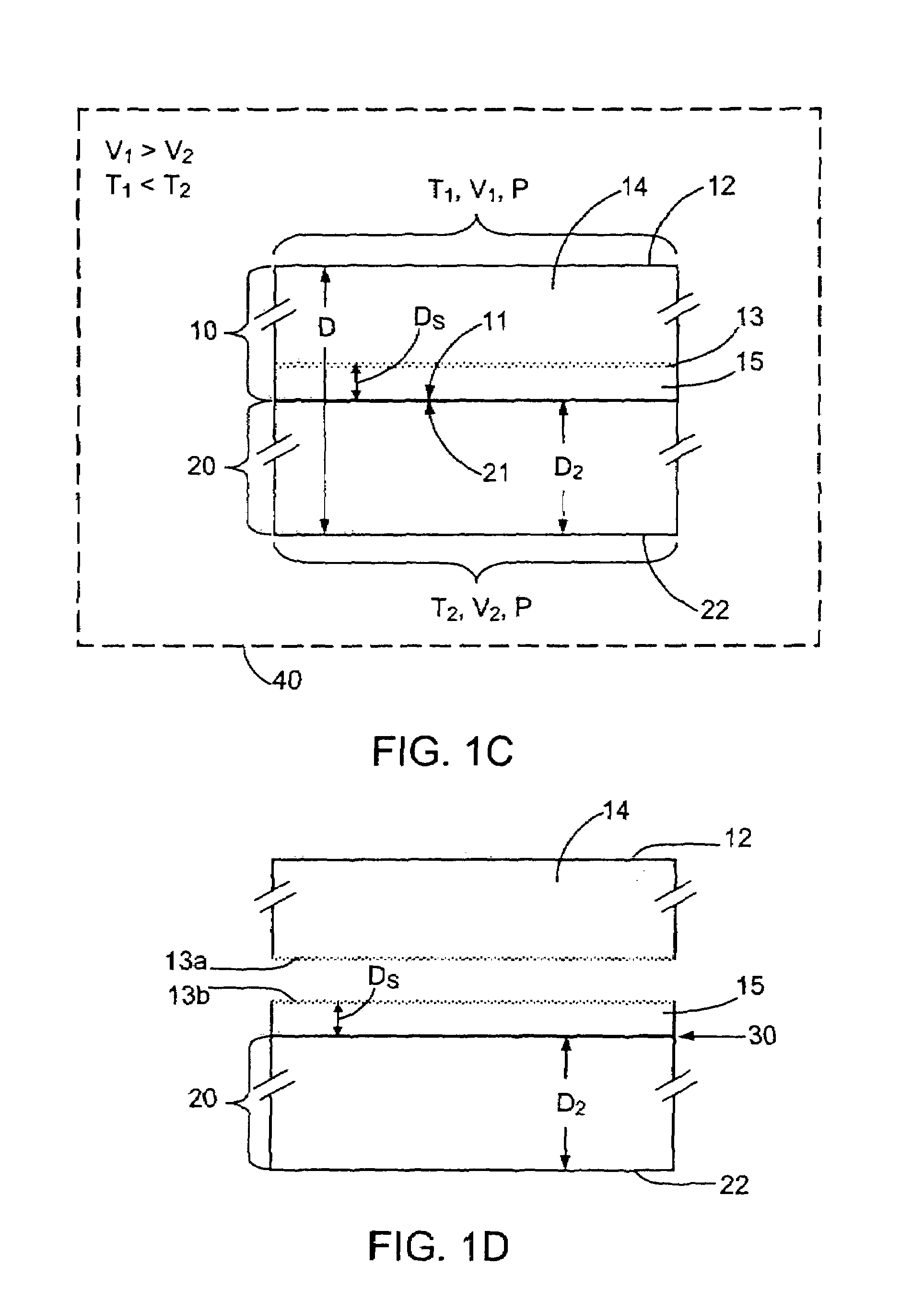
[0254]The experiment of Example 1 was repeated except that the two wafers, glass and silicon, were held at 450° C. and 400° C. respectively. This was done to take advantage of the thermal stress generated by the thermal differential to separate the thin silicon film from the silicon wafer after cooling. The differential heating was achieved by selecting the temperatures of the force-applying plungers of the bonder. The 450° C. and 400° C. values represent the temperatures of the plungers and thus the temperatures at the bottom surface of the glass wafer and the top surface of the silicon wafer, respectively, i.e., the temperatures at surfaces 22 and 12 in FIG. 1C
[0255]In this case, the glass wafer with a 0.4-micron layer of silicon (an SOI configuration) and the remainder of the Si wafer were easily separated, and thus an SOI glass wafer was successfully obtained. This result indicates that the thermal stress generated by a thermal differential is necessary in generating a glass-bas...
example 3
[0257]In this example, the Si wafer was first etched with a pattern of circular islands separated from one another. The islands were about 150 microns in diameter. This patterned wafer was ion implanted and then the process of Example 2 was used to transfer a Si layer about 0.4 microns thick onto the glass wafer. An SOI structure with an excellent bond between the Si layer and glass wafer was created in this case.
[0258]This island technique is expected to be of particular value when making large wafers where a thermal expansion mismatch between the glass and the Si is most likely to lead to delamination or other damage to the SOI structure.
[0259]The pattern etched or otherwise formed in the silicon wafer may be any geometric pattern which produces isolated islands of silicon. The size and the distance between the islands can be adjusted according to the requirements. If desired, a thin layer of silicon may be deposited via standard techniques to establish connectivity between all or...
PUM
 Abstract
Description
Claims
Application Information