Manufacturing method of semiconductor device
a manufacturing method and semiconductor technology, applied in the direction of semiconductor devices, basic electric elements, electrical equipment, etc., can solve the problems of increasing the off-current of the tft, increasing the cost and yield, and increasing so as to reduce the number of steps, reduce the number of processes, and improve the crystallinity
- Summary
- Abstract
- Description
- Claims
- Application Information
AI Technical Summary
Benefits of technology
Problems solved by technology
Method used
Image
Examples
embodiment 1
[0106]Embodiment 1 is described with reference to FIGS. 7A to 9C.
[0107]First, as shown in FIG. 7A, gate electrodes 501 to 503 are formed over a substrate 500. A glass substrate such as barium borosilicate glass or alumino borosilicate glass; a quartz substrate; a stainless steel substrate; or the like can be used as the substrate 500. In addition, a substrate formed from a synthetic resin having flexibility such as plastic typified by PET, PES, and PEN, or acrylic may be used as the substrate 500.
[0108]The gate electrodes 501 to 503 are formed to have a single layer structure of a conductive film or a stacked structure of two or more conductive films. When two or more conductive films are stacked, the gate electrodes 501 to 503 may be formed with a stacked layer of an element selected from tantalum (Ta), tungsten (W), titanium (Ti), and molybdenum (Mo); or an alloy material or a compound material containing the element as its main component. In addition, the gate electrodes may be f...
embodiment 2
[0131]In Embodiment 2, an example of adding a catalytic element more selectively is described with reference to FIGS. 5A to 6B.
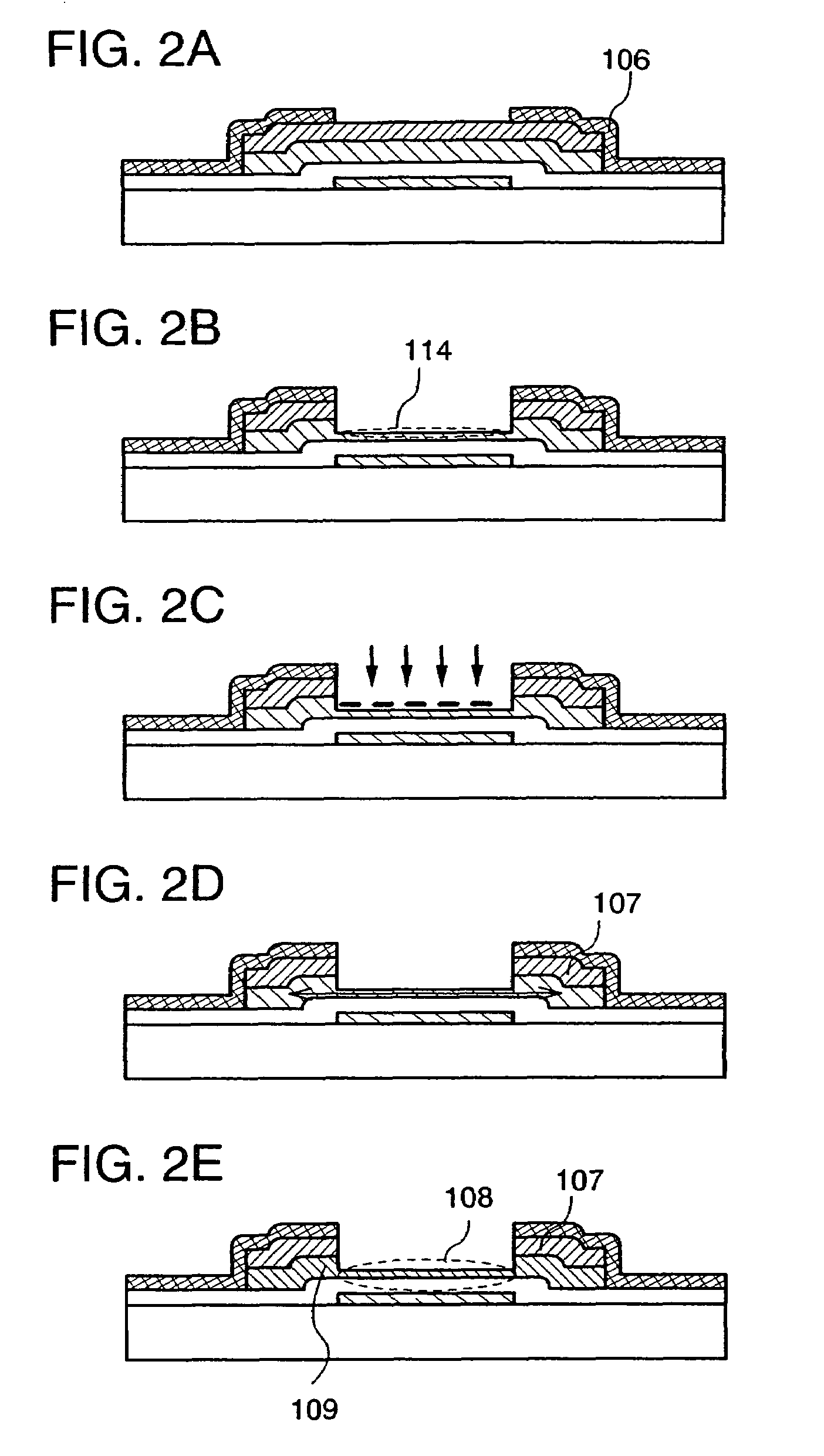
[0132]First, the process up to etching the island-shaped region 113 shown in FIG. 2B is performed according to the process described in Embodiment Mode. Note that the same portions as those in Embodiment Mode are denoted with the same reference numerals (FIG. 5A).
[0133]A mask 201 is formed to cover a region 114 in which a source region and / or a drain region 106 and an island-shaped amorphous semiconductor film 111 are exposed. The mask 201 may be formed using a heat-resistant material because a heat treatment is performed in a later process. For example, silicon oxide, silicon nitride, silicon nitride containing oxygen, or silicon oxide containing nitrogen is used. In this embodiment, the mask 201 is formed with silicon oxide. In addition, the mask 201 is etched to be provided with an opening 200 for adding a catalytic element over the region 114.
[0134]Then,...
embodiment 3
[0152]In Embodiment 3, an example of forming wirings connected to a source electrode and / or a drain electrode using a low melting point conductive material is described with reference to FIGS. 10A and 11.
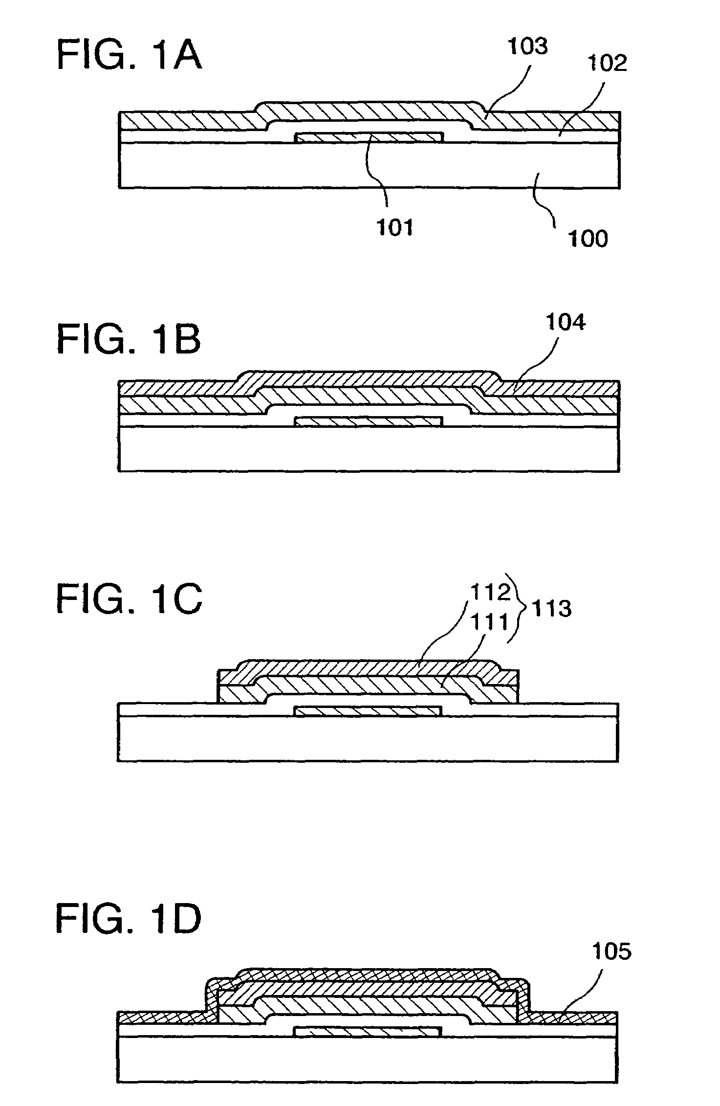
[0153]First, the process up to forming the conductive film 105 shown in FIG. 1D is performed according to the process described in Embodiment Mode. Note that the same portions as those in Embodiment Mode are denoted with the same reference numerals (FIG. 10A).
[0154]A resist mask is formed over the conductive film 105, and the conductive film 105 is patterned to form a source electrode and / or a drain electrode 301. However, wirings are formed in a later process separately from the source electrode and / or the drain electrode 301. Only the source electrode and / or the drain electrode 301 is formed in this process (FIG. 10B).
[0155]An island-shaped region 113 is etched using the source electrode and / or the drain electrode 301 as a mask. The etching method described in Embodiment Mode may ...
PUM
 Abstract
Description
Claims
Application Information
 - R&D
- Intellectual Property
- Life Sciences
- Materials
- Tech Scout
- Unparalleled Data Quality
- Higher Quality Content
- 60% Fewer Hallucinations
Browse by: Latest US Patents, China's latest patents, Technical Efficacy Thesaurus, Application Domain, Technology Topic, Popular Technical Reports.
© 2025 PatSnap. All rights reserved.Legal|Privacy policy|Modern Slavery Act Transparency Statement|Sitemap|About US| Contact US: help@patsnap.com


