Transient control solution for optical networks

a technology of optical networks and transient effects, applied in the field of high-speed optical telecommunication networks, can solve the problems of transient effect, adverse effects downstream, slow response time,

Inactive Publication Date: 2008-10-28
AMERICAN TELEPHONE & TELEGRAPH CO
View PDF20 Cites 22 Cited by
  • Summary
  • Abstract
  • Description
  • Claims
  • Application Information

AI Technical Summary

Benefits of technology

[0018]There is a need, therefore, for simple, low-cost, and high-performance transient control in dynamic optical networks. Specifically, a method and apparatus are needed for suppressing the transient effect and the related inter-channel SRS induced spectrum tilt change in the surviving optical channels, caused by upstream fiber cut or equipment failure.

Problems solved by technology

The slow gain dynamics, however, also result in a slow response time.
In the presence of a large instantaneous change in input power to the EDFA, the slow response time can cause adverse effects downstream.
In an extreme case, a fiber cut or equipment failure upstream from the OADM may occur, causing a transient effect on the transmission of surviving channels in the downstream link, i.e., in those channels added at the OADM.
Due to the transient effect, the surviving channels may also experience transmission errors and, if severe enough, these errors may cause unwanted protection switching in optical networks.
Though the pump control method may be adequate to correct slow or small fluctuations in amplifier gain over time, it is inadequate to handle transient effects on surviving channels resulting from fiber cuts or equipment failure upstream from the amplifier.
In other words, the slow dynamics of EDFA, though advantageous in that the gain is subsequently undisturbed by the modulation of the transmission signal, pose a problem in the event of a fiber cut or equipment failure.
The pump control method is particularly inadequate in the case of the large channel count drop that occurs when there is a fiber cut or equipment failure in an optically amplified WDM network.
Two problems arise in this case.
A spectral power distribution as well as the optical power at the input to the downstream optical amplifier changes, therefore, when fiber cuts or equipment failures occur.
First, the sudden large drop in optical input power to an amplifier downstream of the OADM cannot be accommodated by the pump control method due to the slow gain dynamics of the EDFA.
Second, the large change in the spectral power distribution results in a large change of stimulated Raman scattering (SRS) induced spectrum tilt in the downstream transmission fiber not compensated for by the pump control method.
Consequently, both the transient gain and SRS spectrum tilt change could cause transmission errors for the channels transmitted to a downstream optical fiber link and undesired protection switching in the optical network.
The control speed of VOA, however, cannot match the spectrum tilt change and the algorithm to simultaneously control both the pump power and VOA is very complicated and inadequately slow.
Using multiple filler lasers occupying several WDM wavelength slots, therefore, reduces transmission capacity.
The phenomenon ultimately limits the maximum optical power that can be launched into the fiber.
Moreover, inhomogeneous broadening of optical amplifiers and the resulting spectral hole burning can cause gain variations at the optical wavelength of the filler laser, additionally limiting the capability of the filler laser control technique.
As a result, the filler laser control method is complicated, costly, inefficient, and requires a reduction of the total transmission capacity of the optical network.
In summary, these and other conventional methods which have been employed in an attempt to mitigate the transient effect are complex, costly, and largely incapable of error free performance.

Method used


Image

  • Transient control solution for optical networks
  • Transient control solution for optical networks
  • Transient control solution for optical networks

Examples


Embodiment Construction

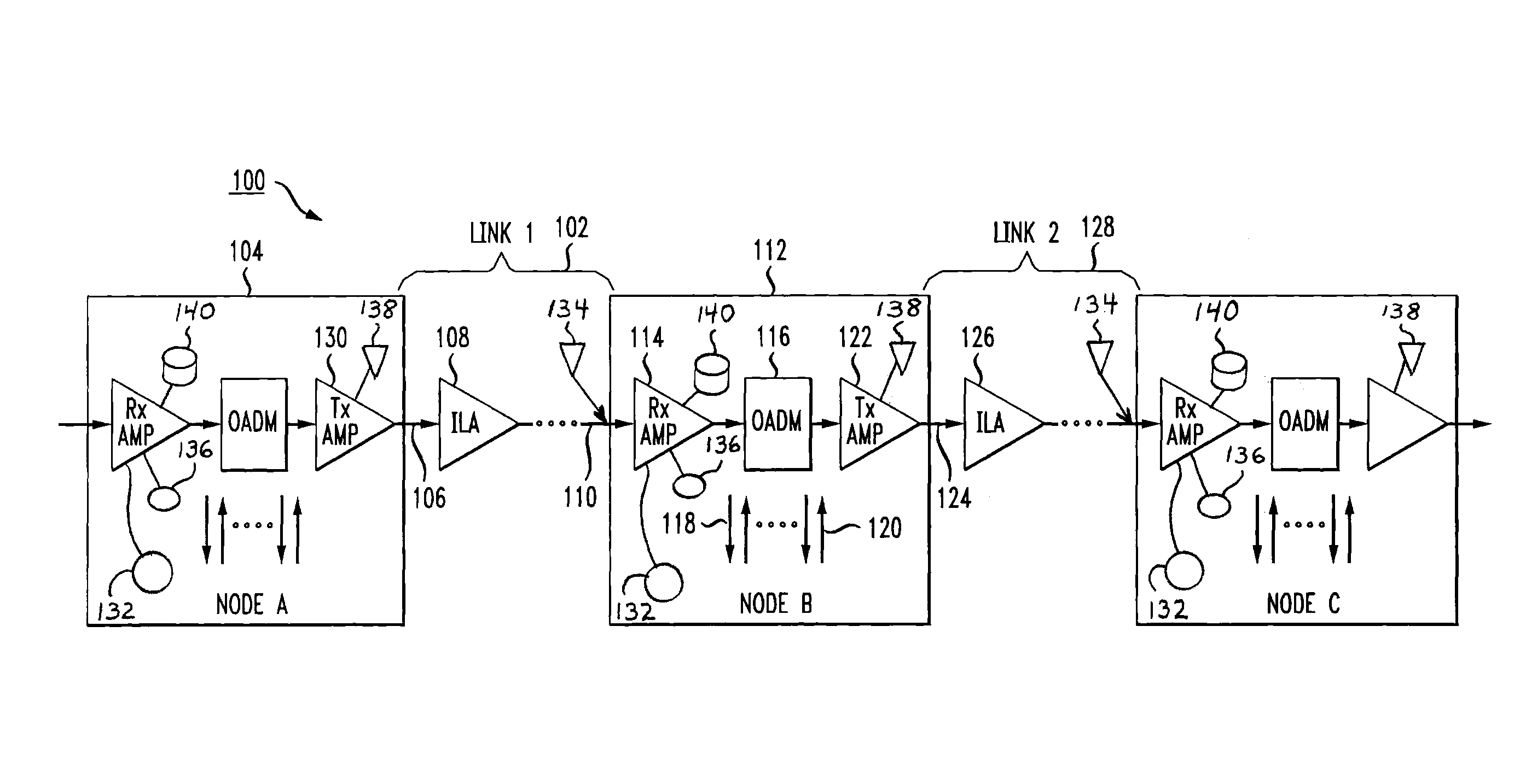
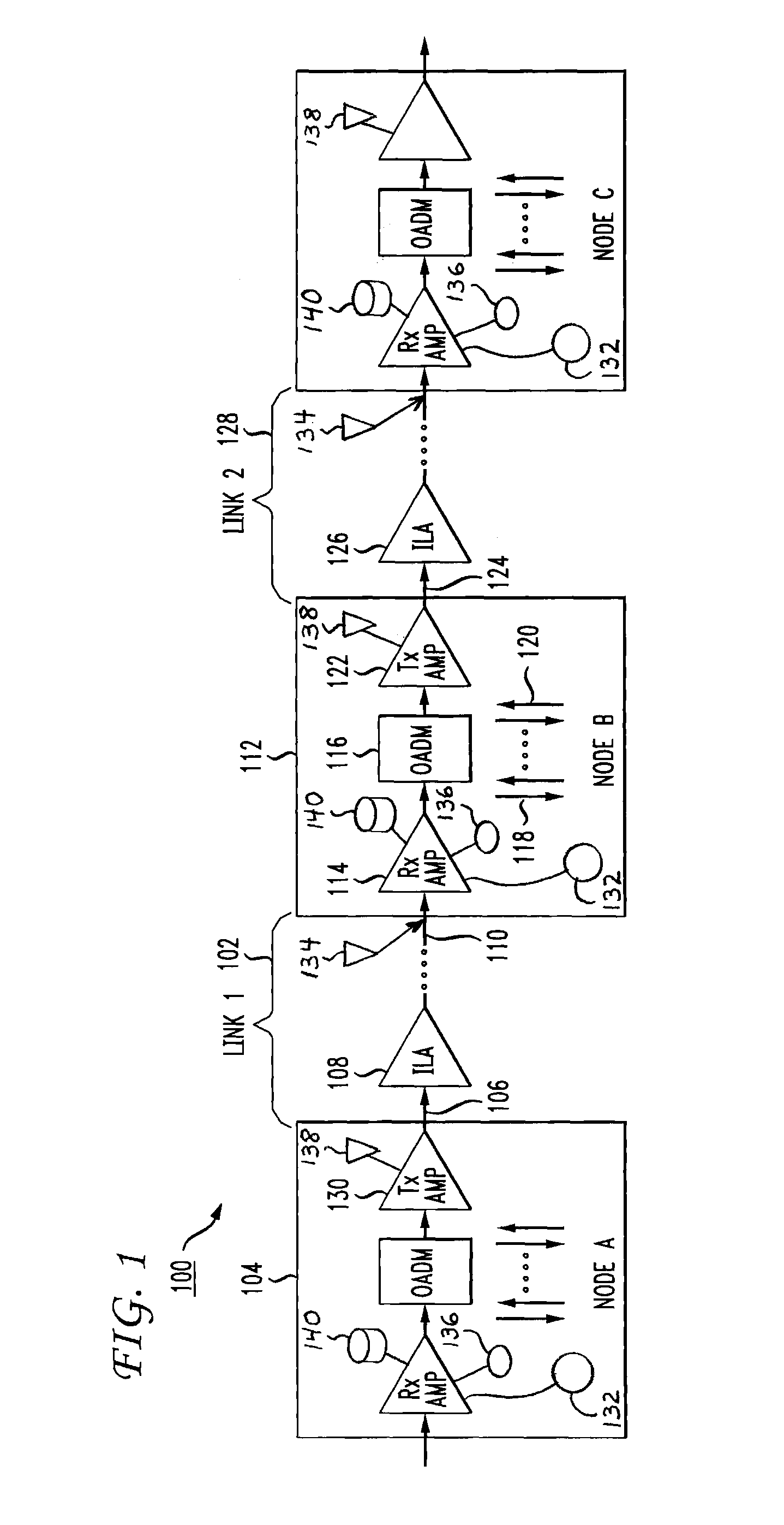
[0031]FIG. 1 shows two links and three nodes of an optically amplified wavelength division multiplexing (WDM) network 100 in accordance with the present invention. A node, also referred to as an optical add / drop multiplexing (OADM) node includes at least one receiver amplifier, an OADM module, and at least one transmitter amplifier. A link according to the present invention includes an optical fiber connecting two nodes and may include in-line optical amplifiers. Only one direction is depicted in FIG. 1 and each of the nodes shown represents a simple two-degree optical add / drop multiplexing (OADM) in one embodiment of the present invention.

[0032]Each optical channel in the WDM network is centered at a particular wavelength. The OADM module operates to drop, pass through, or add a channel according to its corresponding wavelength, or equivalently, its optical frequency. For example, for a channelized OADM with channel spacing of about 50 GHz, the corresponding bandwidth could be abou...


PUM


Abstract

An optically amplified wavelength division multiplexing network has the functionality to add/drop channels at the optical add/drop multiplexing (OADM) nodes. The OADM node includes a receiver amplifier, an OADM module, and a transmitter amplifier. Once the OADM node detects a loss of signal (LOS) due to a fiber cut or network element failure upstream, the receiver amplifier is kept in operation as a noise source. The output of the receiver amplifier is immediately raised by increasing pump power to compensate for the LOS. The noise power received at the transmitter amplifier from the receiver amplifier is substantially equal to the signal power expected before LOS. The transient effect of downstream optical amplifiers is therefore completely suppressed and the inter-channel stimulated Raman scattering (SRS) induced spectrum tilt does not change. After the noise power is raised, the receiver amplifier may be shut down at a speed much slower than the speed of downstream amplifier control circuitry.

Description

CROSS-REFERENCE TO RELATED APPLICATION[0001]This application claims the benefit of U.S. Provisional Application Ser. No. 60 / 503,959, filed on Sep. 18, 2003, which is incorporated herein by reference.FIELD OF THE INVENTION[0002]The invention relates to the field of high-speed optical telecommunication networks, and more particularly to a method and apparatus for suppressing the transient effect in surviving optical channels in the event of a fiber cut or network node failure.BACKGROUND OF THE INVENTION[0003]In optical telecommunication networks that use wavelength division multiplexing (WDM), multiple optical channels are carried on a single optical fiber. The single optical fiber is included in an optical fiber link, which includes the optical fiber and optical amplifiers and any other optical components between two connecting points or nodes along an optical transmission line. Each channel operates at a different wavelength in the optical fiber. New channels may be added and existi...

Claims


Application Information

Patent Timeline
Patent Type & Authority Patents(United States)
IPC IPC(8): H04J14/02
CPCH04J14/0217H04J14/0221H04J14/0287H04J14/028
Inventor STANGO, JOSEPH T.ZHANG, GUODONG
Owner AMERICAN TELEPHONE & TELEGRAPH CO
Why Eureka
Try Eureka