Apparatus and method for controlling wireless communication signals

a wireless communication and antenna technology, applied in the direction of channel coding adaptation, transmission monitoring, multiple modulation transmitter/receiver arrangement, etc., can solve the problem of urgent search for a method for increasing the wireless link and its related network capacity, the concept of a “pico cell” (approximately 100 meters in radius) has failed in the deployment of the cellular system, etc., to reduce the power level of the wireless transmission channel and reduce the capacity of the wireless signal

Active Publication Date: 2008-11-18
COMS IP HLDG LLC
View PDF2 Cites 127 Cited by
  • Summary
  • Abstract
  • Description
  • Claims
  • Application Information

AI Technical Summary

Benefits of technology

[0031]According to another aspect of the present invention, there is provided a method of generating a signal for carrying data for wireless transmission, comprising monitoring a parameter indicative of a quality of said wireless signal, comparing said quality with predetermined value and decreasing the capacity of the wireless signal if said parameter falls below a predetermined value.
[0032]According to another aspect of the present invention, there is further provided a method of c

Problems solved by technology

That response leaves the last mile especially the wireless link as a potential bottleneck.
As a consequence, the task of searching for a method for increasing the wireless link and its related network capacity is urgent.
High frequency reuse can be achieved by reducing cell size, however, that means increasing the number of expensive Base Transceiver Stations (STS).
This notion of “Pico cell” (approximately 100 meters in radius) has failed completely in cellular system deployment due to its high cost.
This makes the design of the system throughout the transmitter to receiver more complicated.
For example, designing a linear Power Amplifier (PA) for 64 QAM for the Customer Premise Equipment (CPE) is already very challenging, bearing in mind that the PA is the most expensive component in a transmitter design.
The other limiting factor that prevents very high order QAM from being applied in wireless systems is that the cost of driving down the phase noise in the Phase Loc

Method used


Image

  • Apparatus and method for controlling wireless communication signals
  • Apparatus and method for controlling wireless communication signals
  • Apparatus and method for controlling wireless communication signals

Examples


Embodiment Construction

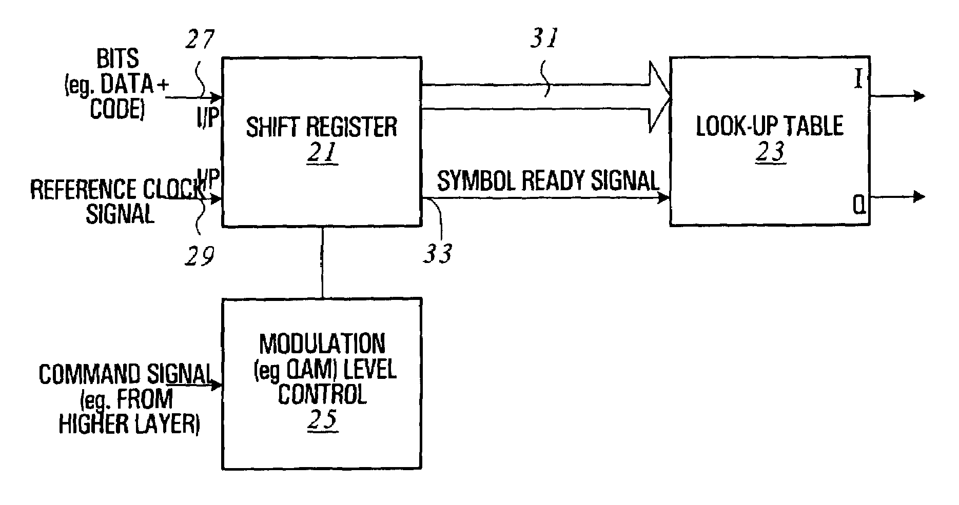
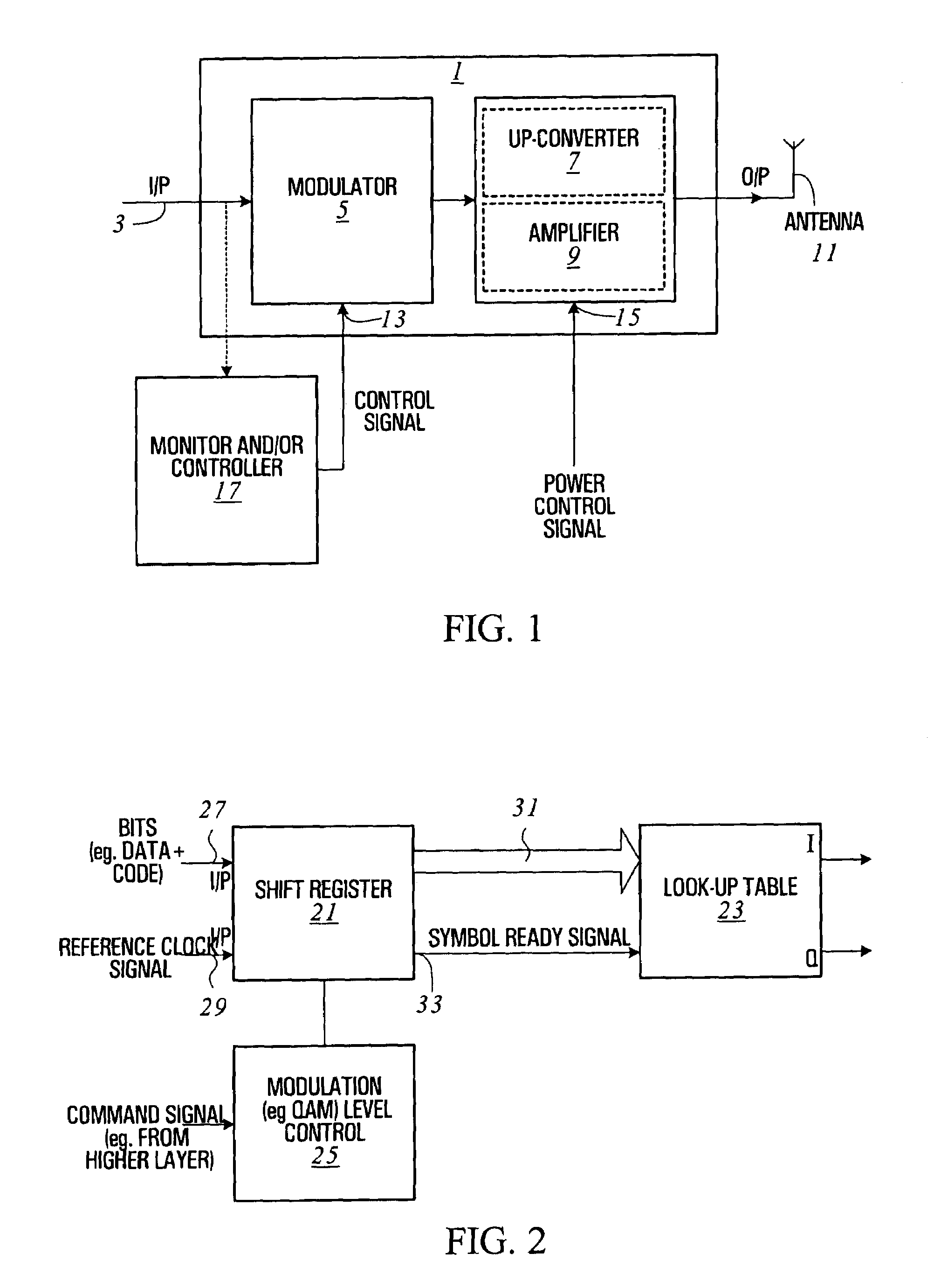
[0058]FIG. 1 shows a wireless transmitter according to an embodiment of the present invention. The transmitter 1 has an input 3 for receiving data for transmission over a wireless communication link, a modulator 5 for generating a signal representative of the data, an up-converter 7 for up-converting the signal from the modulator to the desired frequency for RF transmission, and an amplifier 9 for amplifying the up-converted signal prior to transmission from an antenna 11. In this embodiment, the modulator 5 is capable of varying the data or bit carrying capacity of the wireless communication channel by varying the number of bits represented by each symbol or change of state in the output signal of the modulator. For example, a particular sequence of a given number of binary bits may be represented by a particular phase and / or amplitude of a signal, and the number of bits that can be represented by each or both of these parameters depends on the particular modulation scheme used. Th...


PUM


Abstract

An apparatus and method for controlling wireless communication signals is provided, in which a wireless transmitter in a communication network generates a signal carrying data for wireless transmission, and is capable of varying the data carrying capacity of the wireless transmission channel in response to the quantity of data received for wireless transmission. A monitor is provided to monitor the quantity of received data and the capacity of the communication channel is increased if the monitored quantity exceeds a predetermined threshold. The capacity of the communication channel can be varied by varying the level of modulation and/or by varying the level of code inserted into the data stream. The output power of the wireless transmission signal may be varied in response to the quantity of received data.

Description

CROSS-REFERENCE TO RELATED APPLICATION[0001]This application claims priority from U.S. Provisional Patent Application Ser. No. 60 / 252,463 filed on 22 Nov. 2000.BACKGROUND OF THE INVENTION[0002]With the current “wave” of the commercialization of Internet usage, and the increasing usage of multimedia applications, the traffic demand is seen as a phenomenon which is exploding today. The response from the wired world is the emergence of Dense Wavelength Division Multiplexing (DWDM) technology, which can increase link throughput by one magnitude or more. That response leaves the last mile especially the wireless link as a potential bottleneck. As a consequence, the task of searching for a method for increasing the wireless link and its related network capacity is urgent.[0003]This is why the spectrum efficiency becomes the first consideration for the spectrum license auction in most countries around the world. Whoever has the solution offering higher efficient use of the spectrum will wi...

Claims


Application Information

Patent Timeline
IPC IPC(8): H04Q7/20H04L1/00H04L27/00
CPCH04L1/0003H04L1/0009H04L27/0008
Inventor HUANG, JUNDUXBURY, TOM
Owner COMS IP HLDG LLC
Why Eureka
Try Eureka