Etching method

a technology of etching and substrate surface, applied in the direction of vacuum evaporation coating, heating type, plasma technique, etc., can solve the problem of non-uniform distribution of etching quantity in plane with respect to the surface of the substrate, and achieve the effect of fast etching ra

Active Publication Date: 2009-03-03
SAMSUNG ELECTRONICS CO LTD
View PDF5 Cites 5 Cited by
  • Summary
  • Abstract
  • Description
  • Claims
  • Application Information

AI Technical Summary

Benefits of technology

[0009]The present invention addresses the above problems in the conventional technique, with an object of providing an etching method in which the in-plane distribution of the etching amount becomes uniform, and the etching rate is fast.
[0021]Moreover, by producing the intermediate product on the surface of the substrate, the intermediate product promptly reacts with the etching gas, and the intermediate product is not wastefully exhausted from the vacuum atmosphere. As a result, the etching rate becomes faster than in the conventional method.
[0022]If the second pressure range is set equal to or higher than 6.67×10 Pa (0.5 Torr), the etching gas is adsorbed on the surface of the substrate more uniformly, before introducing the free radicals. As a result, the in-plane distribution of the etching amount becomes more uniform.
[0024]When the pressure in the vacuum atmosphere is in a range of from 1.33×10² Pa (1 Torr) to 1.33×10³ Pa (10 Torrs) inclusive, the production efficiency of free radicals becomes particularly high, thereby increasing the etching rate.
[0025]Moreover, if the etching gas is introduced together at the time of introducing the radical formation gas, the etching gas consumed on the surface of the substrate is replenished, and as a result, the etching efficiency becomes higher.
[0026]Furthermore, if the pressure in the processing atmosphere is maintained constant by controlling the exhaust rate at the time of introducing the radical formation gas, etching is performed stably, and as a result, the in-plane distribution of etching becomes more uniform.

Problems solved by technology

According to the conventional dry etching method, however, the in-plane distribution of the etching quantity with respect to the surface of the substrate becomes nonuniform.

Method used


Image

  • Etching method
  • Etching method
  • Etching method

Examples


example

[0074]An example will be described below to explain the effect of the present invention.

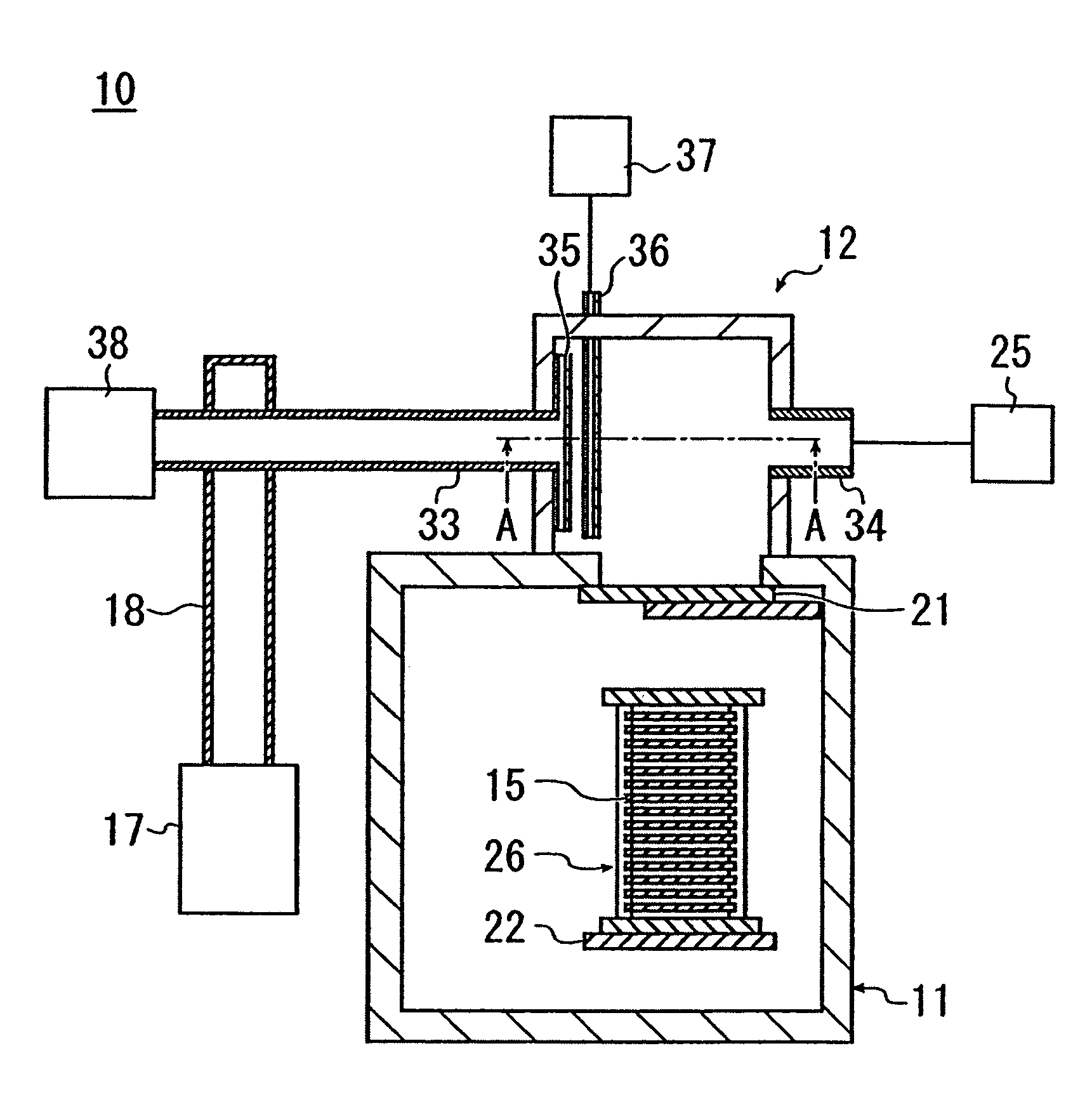
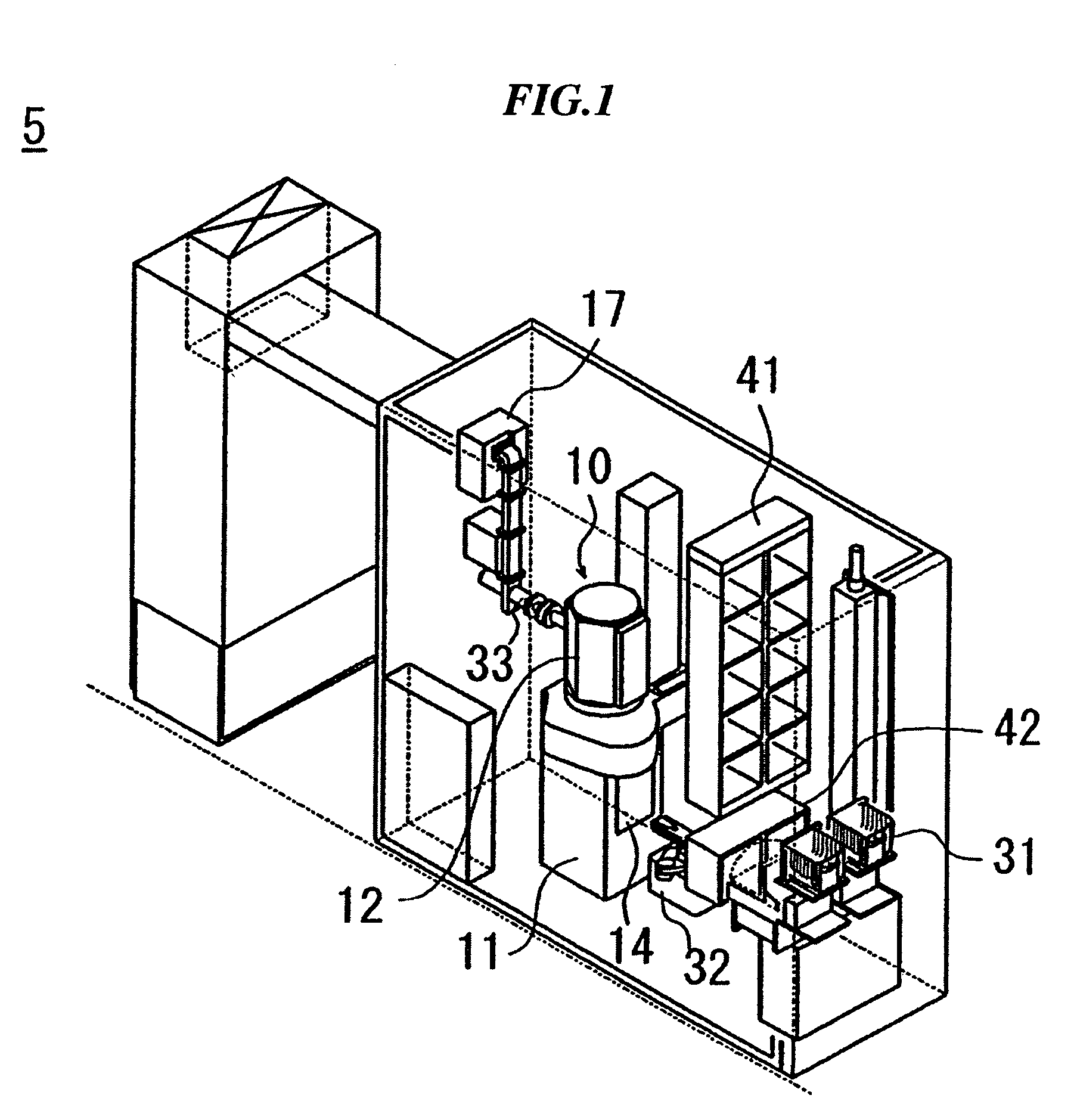
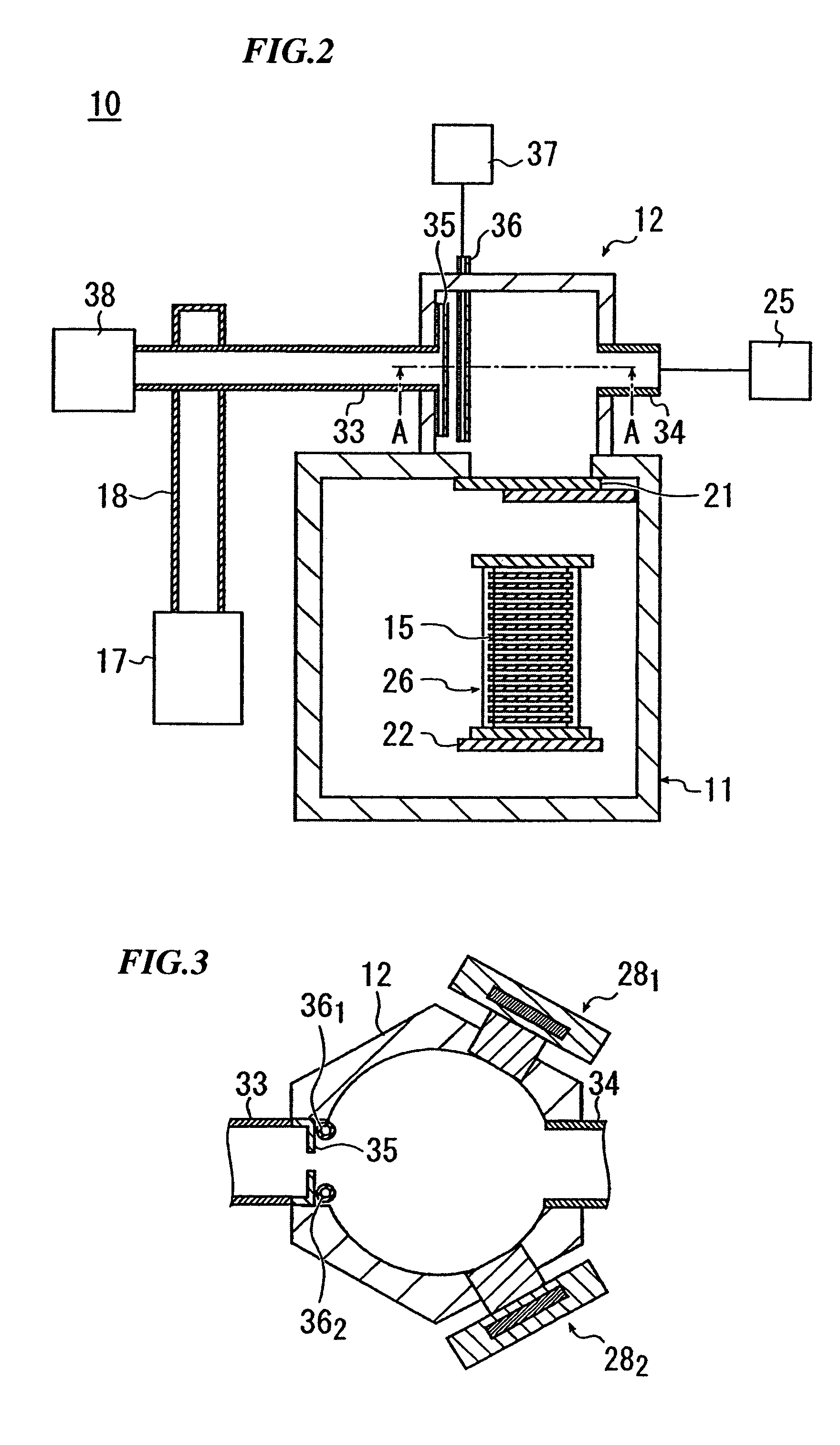
[0075]50 pieces of silicon substrates 15 having a diameter of 8 inches were loaded on one boat 26, and subjected to the etching processing under conditions of the pressure before introduction of the etching gas and the pressure at the time of heating each being 4 Pa (0.003 Torr), the pressure at the time of introducing the free radicals being 4×10² Pa (3 Torrs), the adsorption time being one minute, the reaction time being 330 seconds, the flow rate of the etching gas in the adsorbed state and the reacted state each being 4 slm (slm=liter / min at 0° C.), the flow rates of the radical formation gas and the carrier gas in the reacted state being respectively 1.3 slm and 3.9 slm, the heating temperature being 130° C., and the switched on time of the lamp heaters 281 and 282 being 330 seconds.

[0076]In each substrate 15, the film thickness of the silicon oxide film before etching and the film thickness...


PUM

PropertyMeasurementUnit
pressureaaaaaaaaaa
pressureaaaaaaaaaa
pressureaaaaaaaaaa

Abstract

In this etching method, since an etching gas is introduced before introduction of free radicals into a processing chamber, the etching gas has been adsorbed on the surface of substrates when the free radicals are introduced. Accordingly, the free radicals react with the etching gas adsorbed on the surface of the substrates, and the reaction proceeds uniformly on the surface of the substrate. As a result, nonuniform etching does not occur on the surface of the substrate. Moreover, since the reaction between the etching gas and the free radicals occurs on the surface of the substrate, an intermediate product produced according to the reaction between the etching gas and the free radicals reacts with an etching object promptly. Therefore, the intermediate product is not exhausted from the processing chamber 12 excessively, and hence the etching efficiency is high. As a result, according to this etching method, not only the in-plane distribution of the etching amount becomes more uniform, but also the etching rate is increased more than in the conventional etching method.

Description

BACKGROUND OF THE INVENTION[0001]1. Field of the Invention[0002]The present invention relates to an etching method, and particularly relates to a dry etching method. Priority is claimed on Japanese Patent Application No. 2004-5219 filed on Jan. 13, 2004, the content of which is incorporated herein by reference.[0003]2. Description of Related Art[0004]Conventionally, the dry etching method has been widely used for etching an etching object arranged on a surface of a substrate (see Japanese Unexamined Patent Application, First Publication Nos. 2001-284307 and 2003-124172).[0005]For example, when an etching object formed of a silicon oxide film formed on a surface of a silicon substrate is etched, there is a method in which the substrate is first arranged in a processing chamber, and after a vacuum atmosphere is formed in the processing chamber, an intermediate product reacting with the etching object is produced in the processing chamber. For example, when free radicals of a hydrogen ...

Claims


Application Information

Patent Timeline
Patent Type & Authority Patents(United States)
IPC IPC(8): B44C1/22H01L21/00H01L21/3065H01L21/302H01L21/311H01L21/461H01L21/768H01L23/522
CPCH01L21/31116H01L21/67063E06B7/098F24F2013/207
Inventor LEE, KWANG-MYUNGYUN, KI-YOUNGCHAE, SEUNG-KIHUH, NO-HYUNHWANG, WAN-GOOHWANG, JUNG-HYUNYANAGISAWA, SHINJITSUTSUMI, KENGOTAKAHASHI, SEIICHI
Owner SAMSUNG ELECTRONICS CO LTD
Why Eureka
Try Eureka