
Noise generator

a noise generator and noise technology, applied in the field of noise generators, can solve the problems of less than optimal stand-alone use as a random generator, inferior frequency stability, and no protection of the noise generator from interference, so as to avoid interference, avoid shunting of the signal path, and avoid interference.

Active Publication Date: 2009-03-31
OPTIS WIRELESS TECH LLC
View PDF8 Cites 11 Cited by
  • Summary
  • Abstract
  • Description
  • Claims
  • Application Information

AI Technical Summary

Benefits of technology

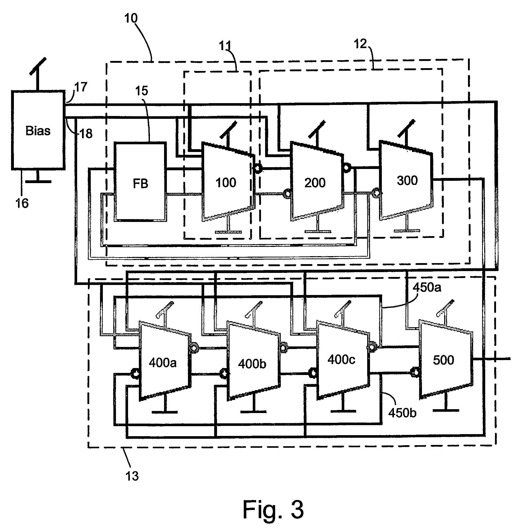
The present invention provides a device for generating a truly random seed for generating a random sequence of bits. The device includes a noise source and an amplifier, which is protected from interfering signals. The noise source is utilized as the bias source of an oscillating means, which provides fast settling time. The device can be integrated into an integrated circuit or used as a stand-alone noise source in any electronic equipment. The invention also provides an optimized sizing of the device that minimizes common-mode induced interference and increases the noise / interference ratio.

Problems solved by technology

Due to circuit imperfections, the thermal noise will contain cycles, such as spurious signals and clock feed-through, rendering it less than optimal for stand-alone use as a random generator.
The oscillators are typically relaxation based or ring oscillators, because of their inferior frequency stability.
Also, no protection of the noise generators from interference is provided.
The disadvantage with the above solutions is in the generation of thermal noise as a seed for generating a random sequence of bits, where the methods are not well suited for digital CMOS technology.
The resistor values have to be high, which means that their area is large if they are implemented on an integrated circuit resulting in a proneness to pick up substrate and other capacitively coupled interference.
Further, not all CMOS technologies provide suitable resistors.
The reverse biased PN junction used as a noise source often rely on carrier multiplication to amplify the noise, resulting in high noise levels, which are noisy with a wide noise bandwidth.
Unfortunately no suitable junction with a low enough breakdown voltage is available in a standard digital ASIC technology.

Method used


Image

  • Noise generator
  • Noise generator
  • Noise generator

Examples


Embodiment Construction

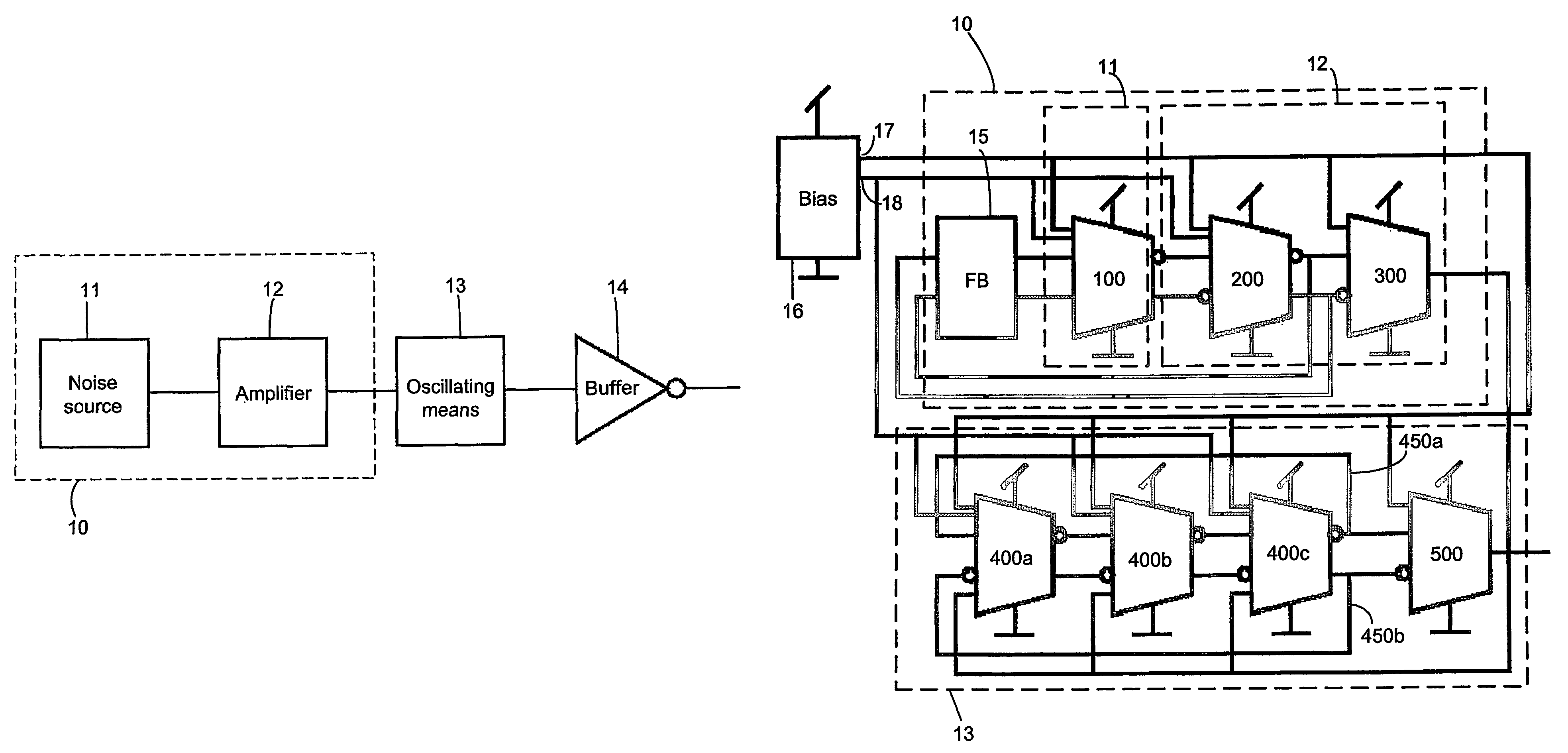
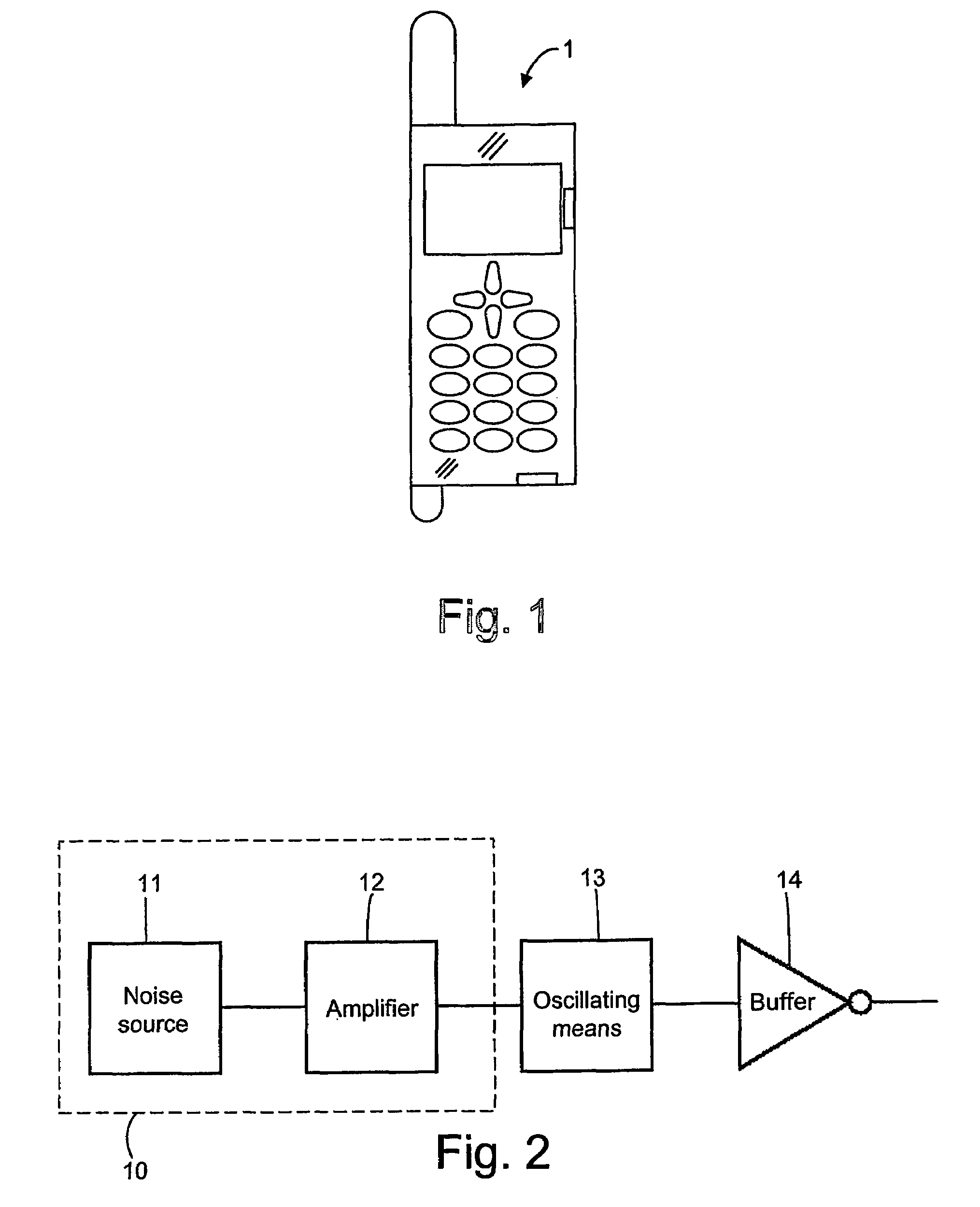
[0033]FIG. 1 illustrates an electronic apparatus embodied as a mobile telephone 1, wherein the present invention is employed. However, the invention is not limited to a mobile telephone 1, but can be implemented in any electronic equipment employing a noise source. The mobile telephone 1 comprises various circuitry for communicating with other electronic apparatuses through e.g. a mobile telecommunication network. The electronic apparatus may also be embodied as a mobile radio terminal, a pager, a communicator, such as an electronic organizer or a smartphone, etc. For providing secure communication, the mobile telephone 1 comprises a cryptographic block, which may be utilized for encryption and decryption, respectively. Consequently, the mobile telephone 1 is adapted to provide cryptographic functions, which are known per se. A device for generating a noise signal is according to one embodiment of the invention provided as an integrated circuit together with other functional blocks,...


PUM


Abstract

A device for generating a noise signal, which may be used for generating a truly random sequence (10) of bits is disclosed. The device comprises a noise source (11), and an amplifier (12) connected to the noise source (11). The device according noise source according to the invention is protected from interfering signals to provide high noise-interference ratio. Further, the present invention relates to an integrated circuit and an electronic apparatus comprising the device for generating a noise signal according to the invention.

Description

[0001]This application claims the benefit of U.S. Provisional Application No. 60 / 459,447, filed Mar. 31, 2003, the disclosure of which is fully incorporated herein by reference.TECHNICAL FIELD[0002]The present invention relates to a device for generating a seed for a random sequence or bits. More specifically, the invention relates to a noise source being protected from interfering signals so as to provide a truly random seed, which may be utilized for generating random bits.DESCRIPTION OF RELATED ART[0003]Random numbers or bits are usually of the pseudo-random (PN) type, generated by feedback shift registers. Such a PN sequence is deterministic and cyclic, but with a long enough cycle it appears to be random when taking a snap-shot at a random time interval. By seeding the PN generator with a truly random value, the PN code will have better statistical properties. Such a seed can be generated from e.g. thermal noise, which in principle is random. Due to circuit imperfections, the t...

Claims


Application Information

Patent Timeline
Patent Type & Authority Patents(United States)
IPC IPC(8): H03B29/00H03F3/45H03F3/68H03K3/84
CPCH03B29/00H03F3/45H03F3/45188H03F3/4565H03F3/68H03K3/84
Inventor MATTISSON, SVEN
Owner OPTIS WIRELESS TECH LLC
Learn More