
Fluoropolymer barrier material

a fluoropolymer and barrier material technology, applied in the field of fluoropolymer barrier materials, can solve the problems of added processing costs, and inability to meet the needs of materials, and achieve the effects of improving fluoropolymer barrier materials, improving barrier properties, and excellent water vapor permeation resistan

Inactive Publication Date: 2009-04-21
WL GORE & ASSOC INC
View PDF14 Cites 161 Cited by
  • Summary
  • Abstract
  • Description
  • Claims
  • Application Information

AI Technical Summary

Benefits of technology

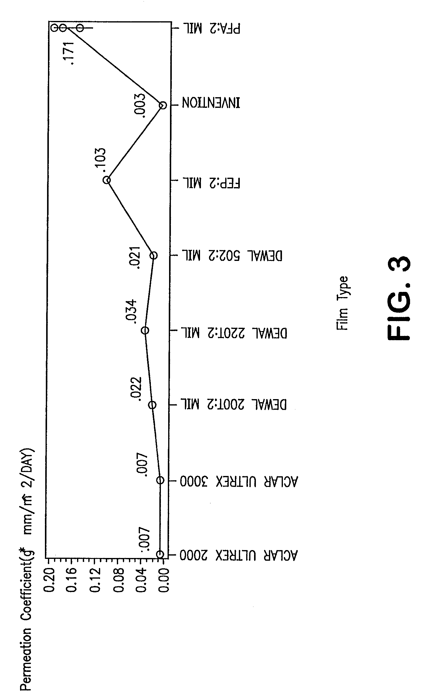
[0016]One objective of the present invention is to provide improved fluoropolymer barrier materials exhibiting enhanced barrier properties, including excellent water vapor permeation resistance (reported as the water vapor permeation coefficient of the material) and strength, which have not heretofore been achieved in the prior art. It will be appreciated by those of skill in the art that the water vapor permeation resistance of a given material is a strong indication of permeation resistance to a wide variety of permeants, and the present invention is in no way limited thereby. Such improved barrier properties are valuable in many applications where resistance to a variety of permeants under aggressive conditions is desirable. The present invention provides improved fluoropolymer barrier materials, preferably comprising dense PTFE sheets or films, with water vapor permeation coefficients of about 0.015 g-mm / m2 / day or less, more preferably about 0.010 g-mm / m2 / day or less, and even more preferably as low as about 0.003 g-mm / m2 / day or less. As noted earlier herein, important benefits to fluoropolymers comprising PTFE materials include a resistance to harsh chemical environments where other polymers quickly degrade and a useful temperature range from as high as 260° C. to as low as near −273° C.
[0017]Another objective of this invention is to enhance the utility of such fluoropolymer barrier materials, preferably comprising dense PTFE sheets or films, by providing improved tensile strengths in orthogonal (i.e., the length and width, etc.) directions. This improvement is of utility in applications requiring improved flex life, load bearing, impact and rupture resistance, notch propagation resistance, cut-through resistance, and abrasion resistance. Improved tensile strengths in both the length and width directions can be achieved in dense PTFE sheets without the need for reinforcing materials that compromise the chemical performance of the finished article. This invention provides for a fluoropolymer barrier material with not only lower water vapor permeation, but also greater tensile strengths in orthogonal directions and greater toughness, along with the excellent chemical and thermal characteristics of traditional dense PTFE sheets or films. Sheets and films of the invention can be made in unusually thin form.

Problems solved by technology

Both monolithic and multi-component, multi-layer films have been constructed; however, to date, no suitable materials have been available which provide the unique combination of thermal stability, strength, thinness and, most importantly, barrier properties as demonstrated by resistance to water vapor permeation.
However, limitations exist with respect to these materials, including the presence of the polyolefin and adhesive layers which contribute undesirable thickness to the final film and added cost during processing.
Moreover, these films have limited chemical and temperature resistance (e.g., maximum thermal stability reported for ACLAR® films is about 215° C.) and limited water vapor permeation resistance.
However, this PVDC film has limited chemical and temperature range (i.e., melt temperature of about 160° C.) and limited water vapor permeation resistance.
PTFE also has a useful temperature range from as high as 260° C. to as low as near −273° C. However, PTFE is characterized by poor mechanical properties such as low tensile strength, poor cold flow resistance or creep resistance, poor cut-through and abrasion resistance and a general poor mechanical integrity that precludes its consideration in many materials engineering applications.
These articles are characterized by low strength, poor cold flow resistance, and poor load bearing capabilities in both the length and width directions of the film.
Processes including paste extrusion of PTFE fine powder have also been used to produce low porosity PTFE articles, however they are also characterized by relatively poor mechanical characteristics.
However, ePTFE is porous and hence cannot be used as a barrier layer to low surface tension fluids since such fluids with surface tensions less than 50 dyne-cm pass through the pores of the membrane.
However, cold flow occurred in the press, non-uniform parts resulted and a density of over 2.1 g / cc was not achieved.
The ePTFE sheet used in U.S. Pat. No. 3,953,566 was stretched or strengthened in only one direction and, hence, the utility of the finished article was severely limited.
However, densities of 2.1 g / cc or greater were not achieved, and the resultant tensile strengths of the finished article were not reported for either the length or width directions.
While the Knox et al. materials exhibit improved barrier properties in the applications described, the methods and articles taught are limited to making thin, flexible PTFE films with uniformly good barrier properties (e.g., a water vapor permeation coefficient on the order of 0.10 g-mm / m2 / day).
Fuhr et al. does not teach or suggest the capability of forming thin PTFE films with good barrier properties.
From the teachings, this method and product are subject to significant variations in processing and product properties, and trial and error is necessary to determine the drawing temperature and draw ratio for each batch of material.
In addition, significant limitations in material size and material strength would result based on the processing techniques taught.

Method used


Image

  • Fluoropolymer barrier material
  • Fluoropolymer barrier material
  • Fluoropolymer barrier material

Examples


example 1

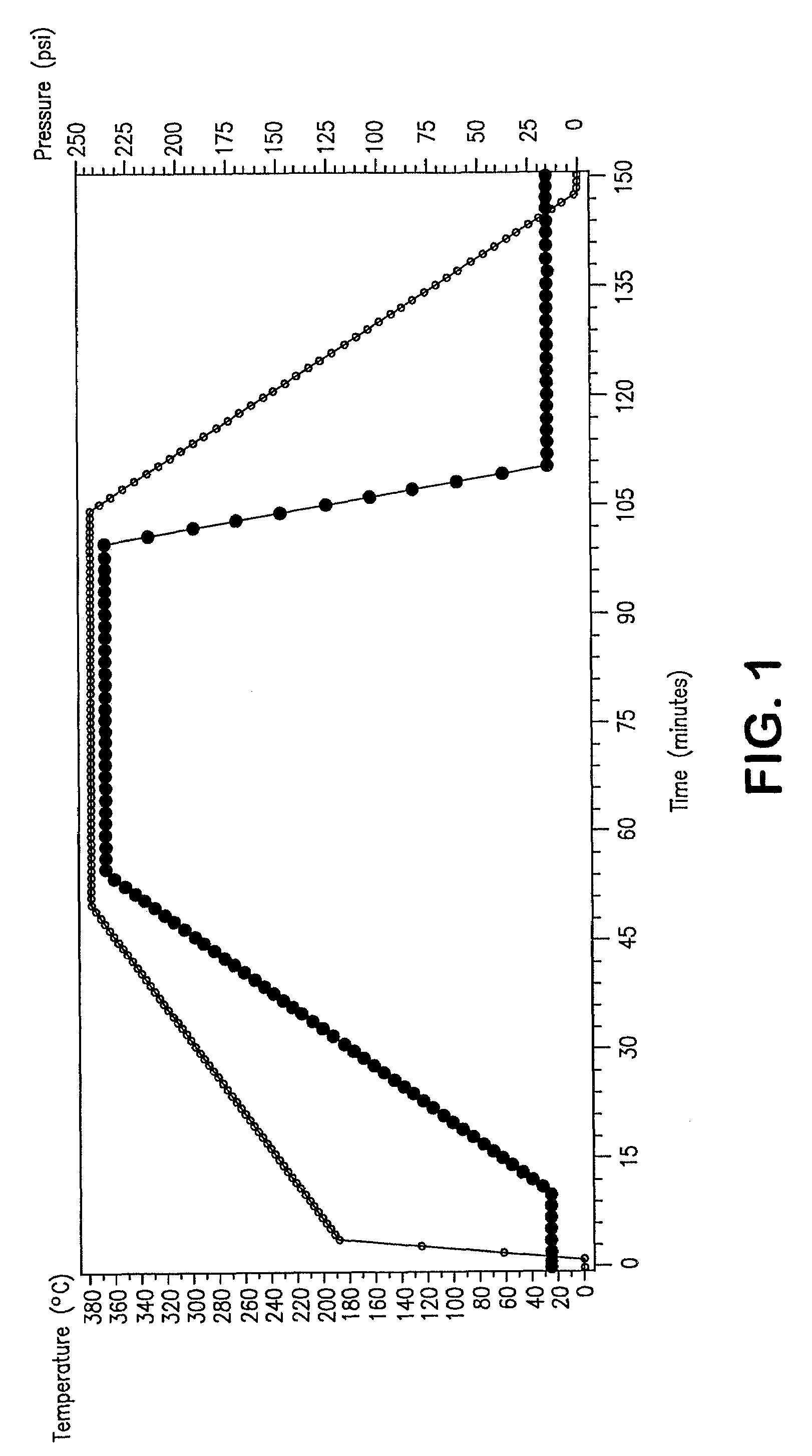
[0064]A 240 lb. aliquot of PTFE fine powder (PTFE 601A, DuPont, Wilmington, Del.) was combined with 44.16 lb. of lubricant (Isopar K, Exxon, Houston, Tex.), subsequently blended, compressed into a cylindrical pellet, and thermally conditioned for 18 hours at a temperature of 49° C. The cylindrical pellet was then extruded through a rectangular die at a reduction ratio of 70:1. The resultant tape was then dried in order to remove the lubricant.

[0065]The dried PTFE tape was then expanded in the y-direction between heated drums at a linear rate of greater than 10% / s, a drum temperature of 225° C. and stretch amount equal to 400%. The tape was then expanded in the x-direction at a linear rate greater than 10% / s, a temperature of about 295° C. and stretch amount equal to 700%. The resulting product was an unsintered ePTFE membrane.

[0066]In order to determine the effect of sintering on the water vapor permeability of membranes, a portion of this unsintered ePTFE membrane was restrained an...

example 2

[0073]A laminate of dense PTFE and perfluoroacrylate (PFA) was made in the following manner. Specifically, a PTFE material was made according to the processing conditions noted for the “A” samples described in Example 1, using a two-pass stretching operation. Following the second pass stretching, the heater was removed from the pantograph. While the stretched PTFE barrier film remained on the pantograph pin body, a PFA film (Part No. 100 LP, 0.001 inch (25 μm) thick, from DuPont, Wilmington, Del.) was placed on one side of the PTFE barrier film. The two films were then subjected to a temperature of 370° C. for 5 minutes to form a laminate of PTFE barrier film and PFA.

example 3

[0074]An unsintered expanded PTFE material was made and densified according to U.S. Pat. No. 5,374,473 Knox, et al. as described in Example 1, except that only a single ply of the unsintered material was subjected to the densification step. The resulting densified material was then stretched according to the processing conditions “A” described in Example 1. The resulting PTFE barrier film had a thickness of 0.1 mils (2.5 μm) and a water vapor permeation coefficient of 0.007 g-mm / m2 / day.


PUM

PropertyMeasurementUnit
melt temperatureaaaaaaaaaa
temperatureaaaaaaaaaa

Abstract

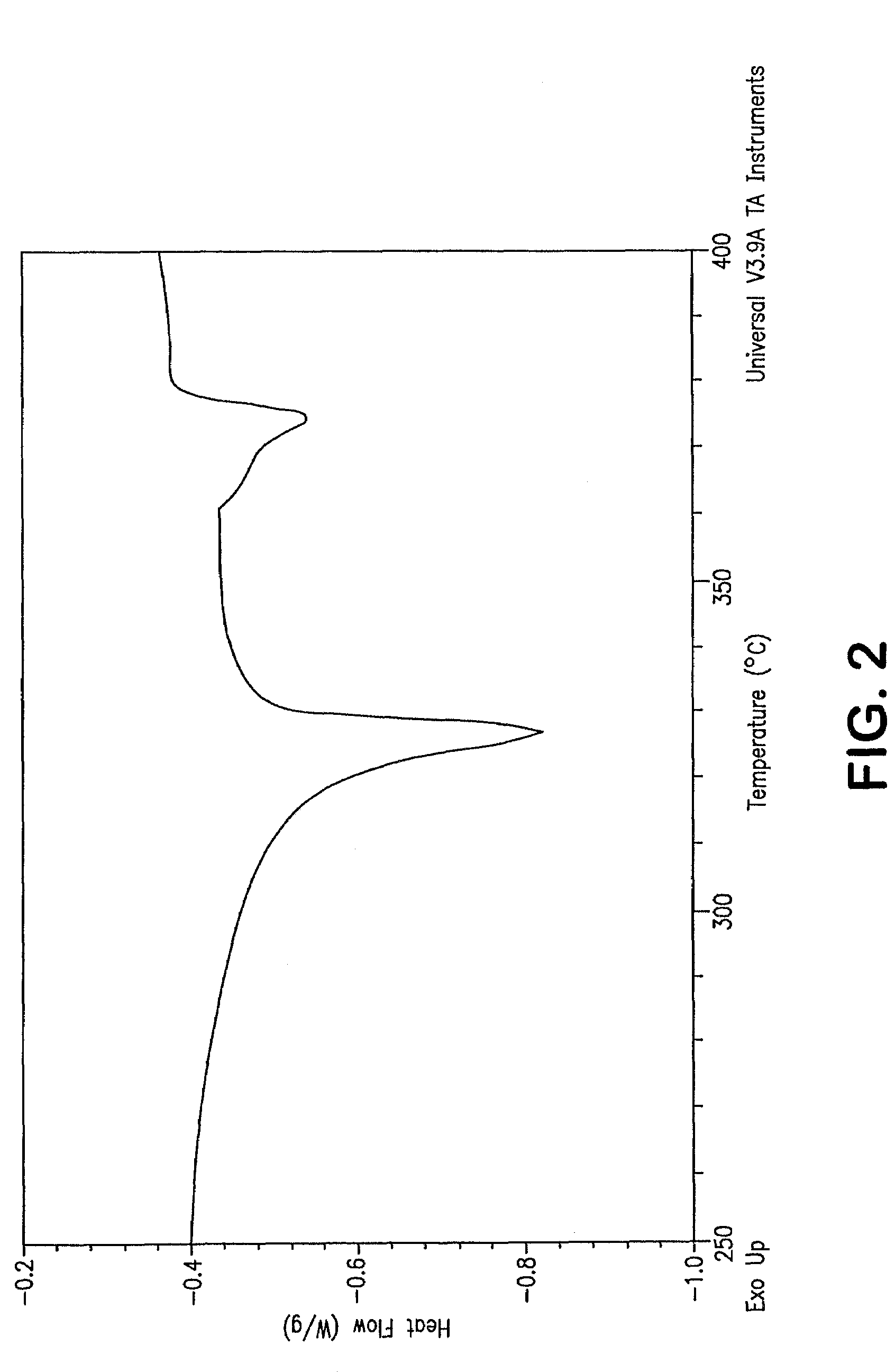
A novel densified fluoropolymer article is described which has a water vapor permeation of about 0.015 g-mm / m2 / day or less, and preferably has a matrix tensile strength of at least 10,000 psi in two orthogonal directions. The articles are made by compressing expanded porous PTFE at pressures, temperatures and times which result in elimination of the pores, and subsequent stretching above the crystalline melt temperature.

Description

RELATED APPLICATIONS[0001]The present application is a divisional application of U.S. patent application Ser. No. 10 / 831,420, filed Apr. 23, 2004 now abandoned.FIELD OF THE INVENTION[0002]The present invention relates to a fluoropolymer barrier material, preferably comprising a dense polytetrafluoroethylene sheet or film, which exhibits very low water vapor permeation and improved tensile properties in both the length and width dimensions (i.e., directions), and to processes for manufacture of said barrier which include a combination of densification, sintering, and stretching of polytetrafluoroethylene.BACKGROUND OF THE INVENTION[0003]The challenge of locating a thermally stable polymer film with excellent barrier properties as well as good mechanical properties for use in a broad range of applications has led researchers in varied directions. Both monolithic and multi-component, multi-layer films have been constructed; however, to date, no suitable materials have been available wh...

Claims


Application Information

Patent Timeline
Patent Type & Authority Patents(United States)
IPC IPC(8): B29C55/12B28B3/00B29C55/00B29C55/02B32B27/00C08J5/18
CPCB29C55/005C08J5/18B32B27/00B29C55/023B29K2027/18Y10T428/265C08J2327/18Y10T428/3154B32B17/10B32B15/085B32B2307/558B32B2307/581B32B27/08B32B27/12B32B2307/518B32B2307/7246B32B2307/54B32B27/322
Inventor KENNEDY, MICHAEL E.HOLLENBAUGH, JR., DONALD L.
Owner WL GORE & ASSOC INC
Learn More