Electrochemiluminescence flow cell and flow cell components
a flow cell and electrochemical technology, applied in the field of electrochemical electrochemical devices, can solve the problems of reducing the measurement sensitivity of an ecl-based flow cell, reducing the efficiency of ecl generation, and reducing the reliability of ecl measurements, so as to improve the ecl generation and application of electrical energy, improve the operation life of the apparatus, and improve the effect of ecl generation and application
- Summary
- Abstract
- Description
- Claims
- Application Information
AI Technical Summary
Benefits of technology
Problems solved by technology
Method used
Image
Examples
examples
[0113]Buffer Compositions: “TPA Assay Buffer” refers to a TPA containing buffer consisting of 0.15 M TPA in a buffer of potassium phosphate, salt and surfactant at a pH of approximately 6.8 (ORI-GLOW® Plus, IGEN International) that provides an appropriate environment for the generation of ECL from Ru(II)(bpy)3 and derivatives. “Cleaning Solution” refers to a solution (0.1 M KOH, 0.15 M NaCl and 0.4% Triton) used to clean the working electrode in an ECL instrument and to remove magnetizable or paramagnetic beads (magnetizable beads and paramagnetic beads are interchangeably referred to throughout) from the surface of the working electrode.
[0114]Calibration Reagents: ORIGEN® M-Series® positive calibrator (PC) was used as a positive control and TPA Assay Buffer was used as a negative control (NC) for the ECL experiments described below. The positive calibrator consisted of 2.8 μm Dynal superparamagnetic beads that are coated with a layer of protein labeled with ORI-TAG® NHS Ester (IGEN...
example i
ECL Measurements
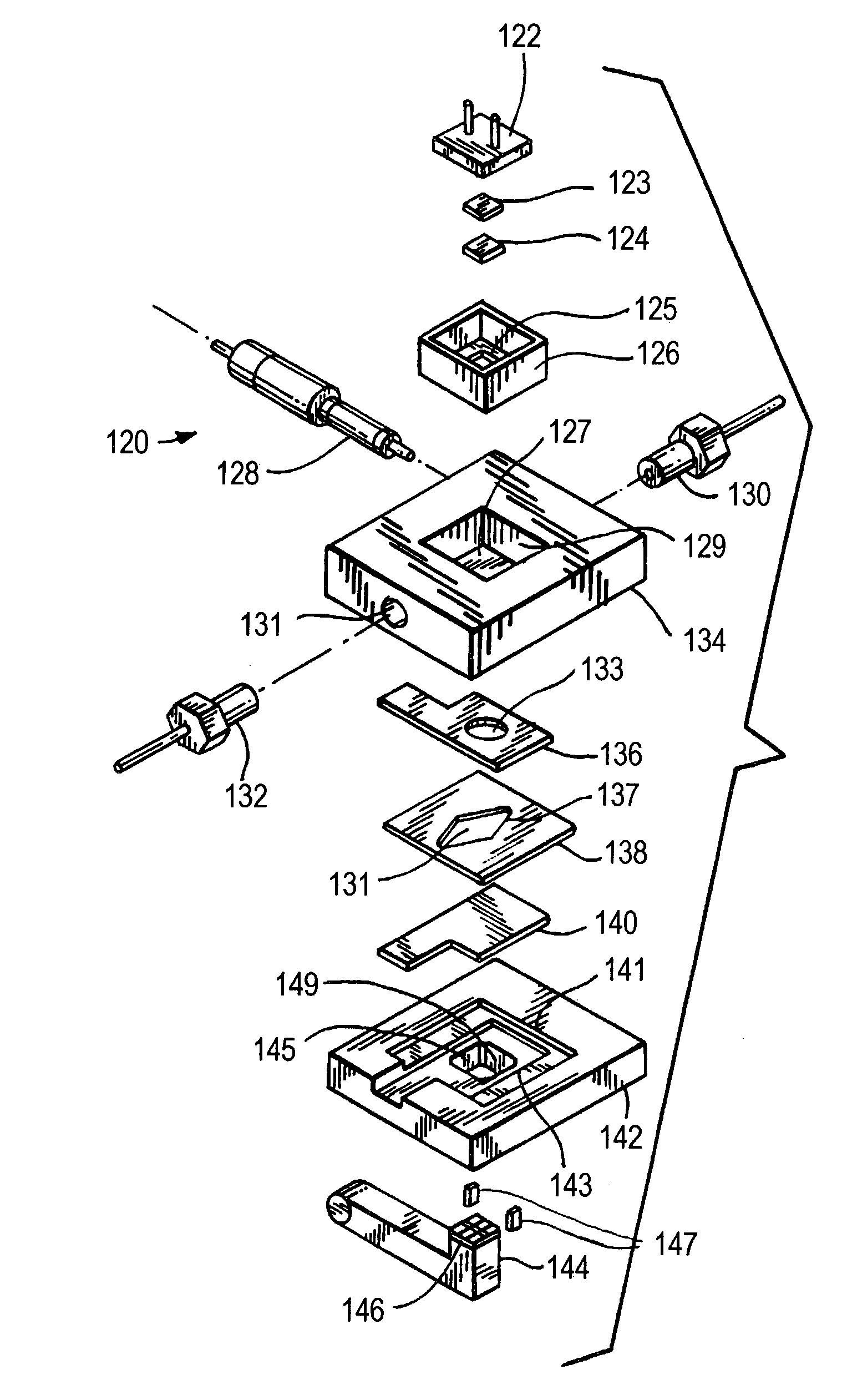
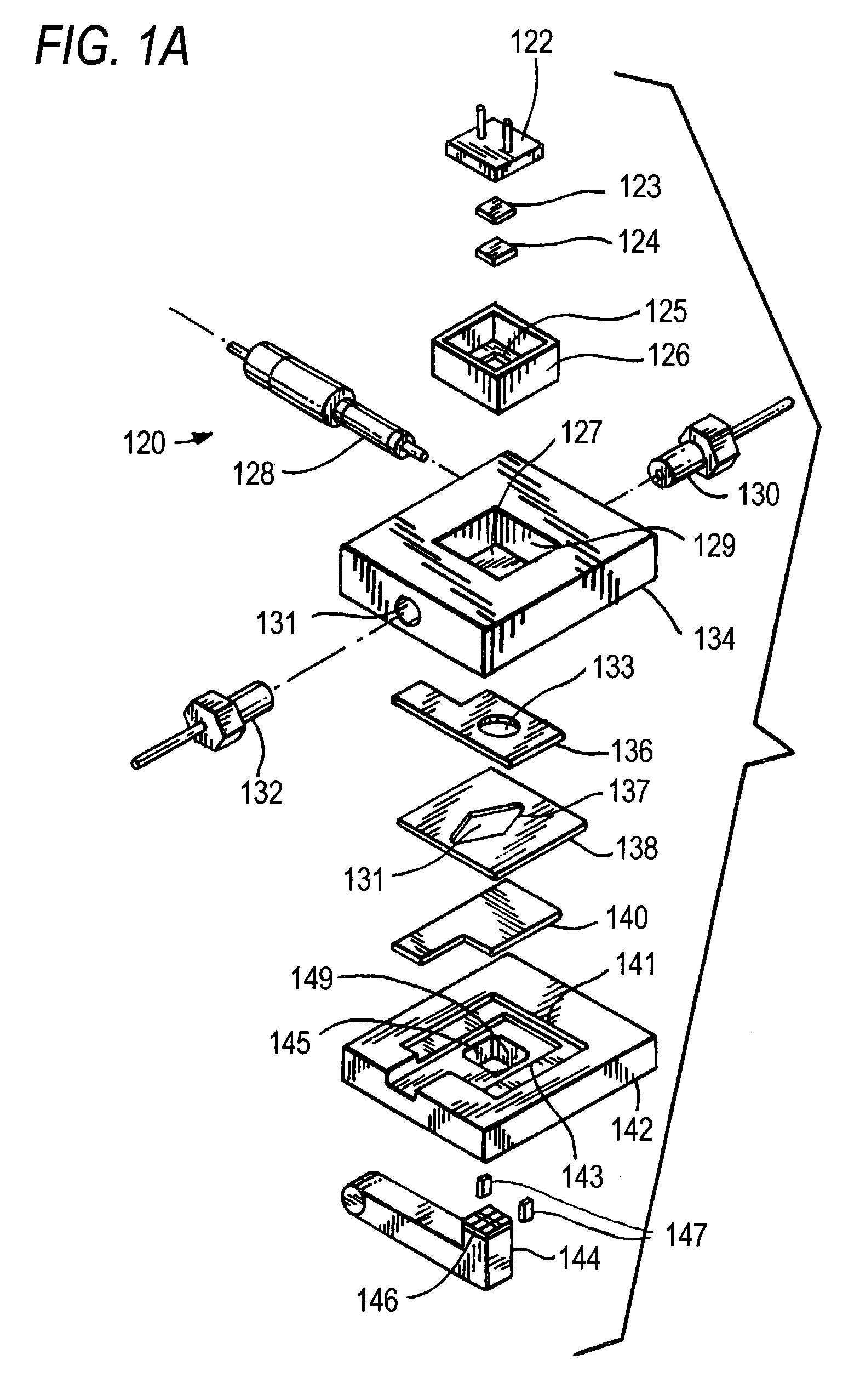
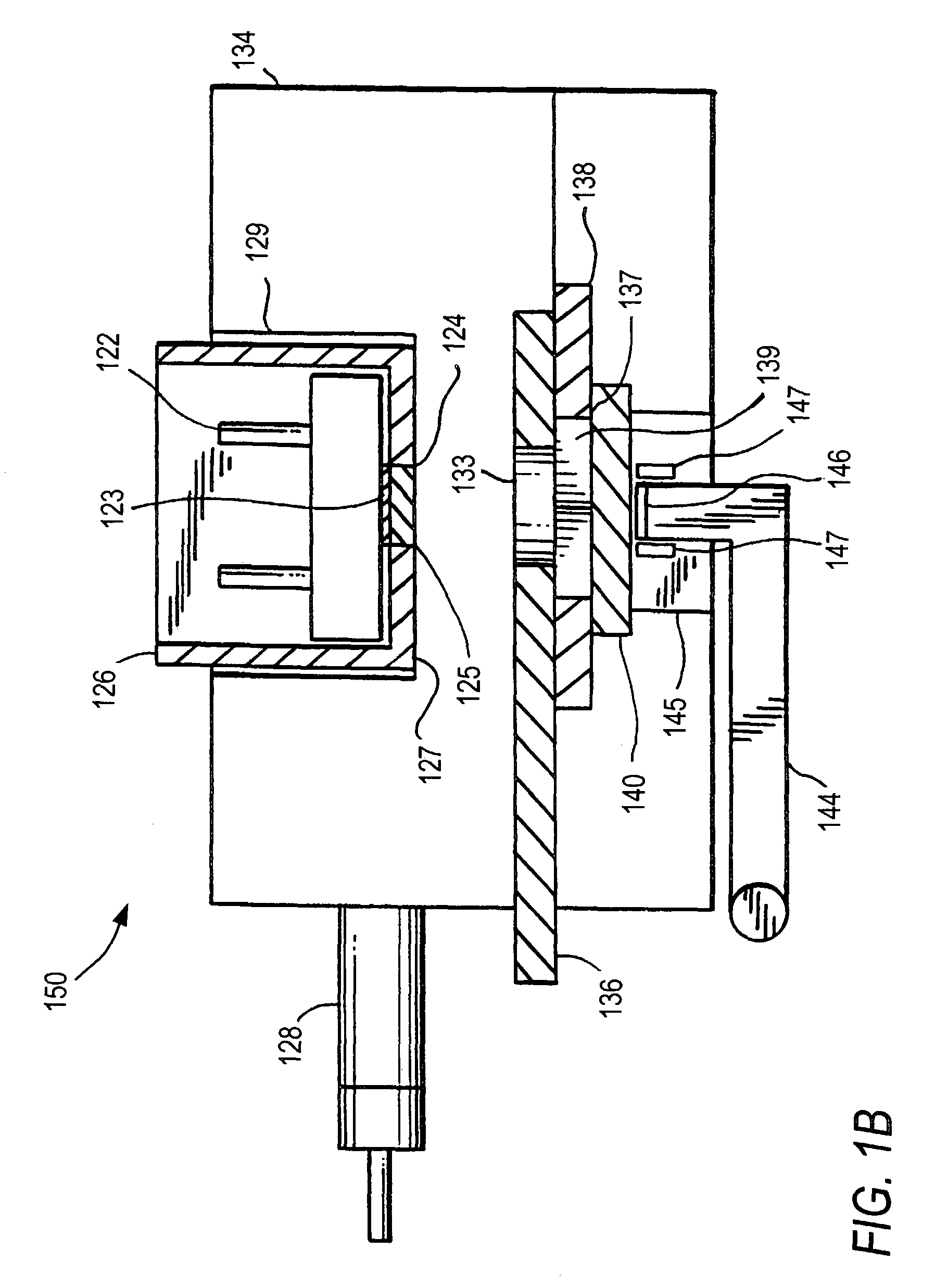
[0116]ECL measurements were conducted using a flow cell from an ORIGEN® M8 Analyzer (IGEN International, Inc.). The flow cell was configured analogously to the flow cell pictured in FIGS. 1A and 1B. The working and / or counter electrodes were either platinum or replaced with alternate materials as described below. The electrochemical potential between the working electrode and an Ag / AgCl reference electrode was controlled using a potentiostat. All values of electrochemical potentials are relative to the Ag / AgCl reference unless otherwise indicated.
[0117]The system fluidic diagram is shown in FIG. 3. System 300 comprises inlet manifold 310, flow cell 320, probe 330, valve 340, pump 350, poppet valve assembly 360, waste receptacle 370, and sample container 380. Inlet manifold 310 comprises valve 312 connected to a source of TPA Assay Buffer, valve 314 connected to a source of Cleaning Solution, valve 316 connected to a source of deionized water, and valve 318 connected ...
example ii
Comparison of ECL Measurements Using Ir, Pt and Pt—Ir Electrodes
[0122]A. Methods: ECL was measured in flow cells having Pt, Ir or Pt-10% Ir electrodes (working and counter) in the presence of positive calibrator (as a positive control to measure the effect of the electrode on ECL signal) or TPA Assay Buffer (as a negative control to measure the effect of the electrode on background signal in the absence of ORI-TAG). Samples (250 μL) were pipetted into the wells of a 96-well plate. The samples (200 μL) were aspirated into the flow cell after resuspension of the beads. There was little difference in the optimal excitation potential for the three materials; a typical value that was used was 1260 mV vs. Ag / AgCl (oxidation).
[0123]Drift was determined over a 100-plate study (about 10,000 samples) for flow cells with Pt or Pt-10% Ir electrodes. Tests were run in batches of eight plates. The first plate (referred to as a “carryover plate”) was designed to measure background signal, signal f...
PUM
 Abstract
Description
Claims
Application Information
 - R&D
- Intellectual Property
- Life Sciences
- Materials
- Tech Scout
- Unparalleled Data Quality
- Higher Quality Content
- 60% Fewer Hallucinations
Browse by: Latest US Patents, China's latest patents, Technical Efficacy Thesaurus, Application Domain, Technology Topic, Popular Technical Reports.
© 2025 PatSnap. All rights reserved.Legal|Privacy policy|Modern Slavery Act Transparency Statement|Sitemap|About US| Contact US: help@patsnap.com


