Carrier for electrophotographic developer, and electrophotographic developer using the same

a technology for electrophotographic developers and carriers, applied in the field of carriers for electrophotographic developers and electrophotographic developers using the same, can solve the problems of reducing the effective carrier surface area, liable to decrease the tribocharging capability of toner particles, and charge leakage, and achieve excellent charge imparting capability and its stability, long life, and high strength

Active Publication Date: 2009-07-28
POWDERTECH
View PDF2 Cites 14 Cited by
  • Summary
  • Abstract
  • Description
  • Claims
  • Application Information

AI Technical Summary

Benefits of technology

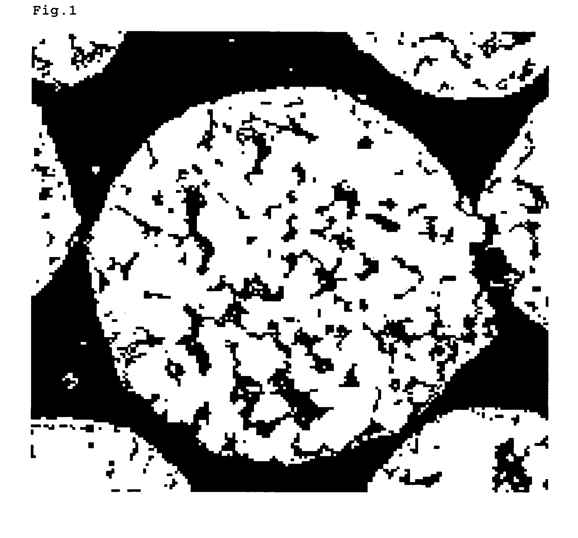
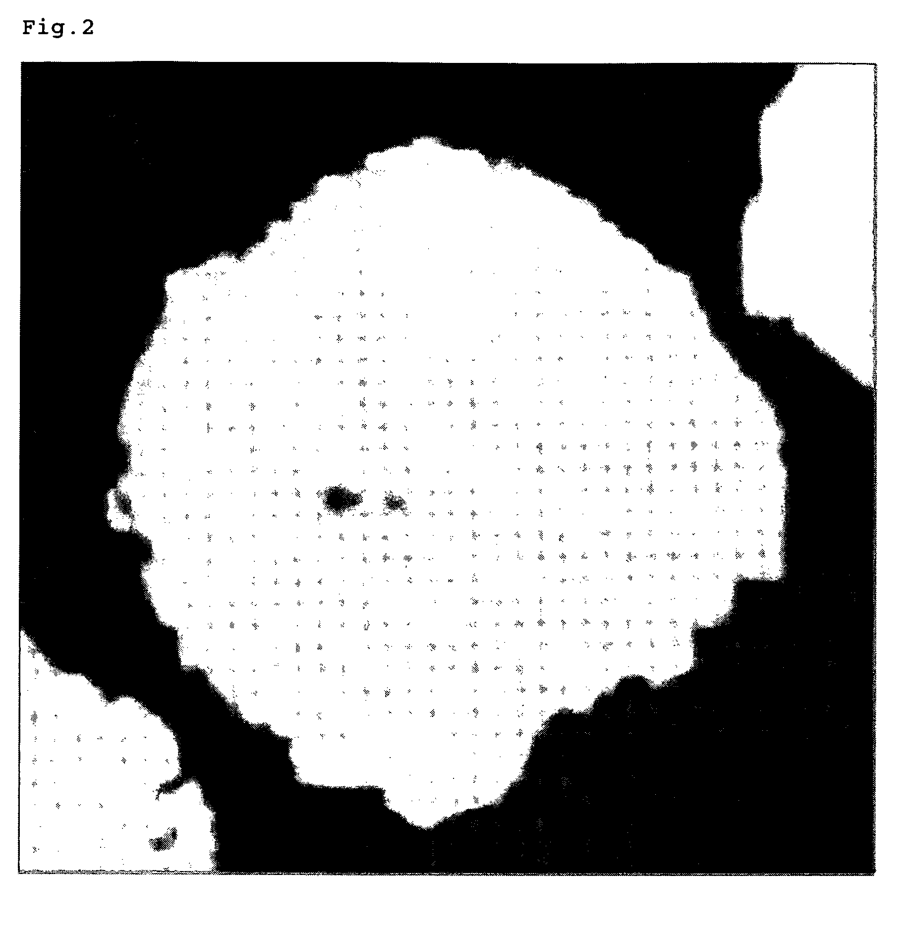
[0037]As a result of extensive studies to solve the above-mentioned problems, the present inventors have found that for maintaining high-quality images for a long period, the above-mentioned objects can be accomplished by making a resin-filled ferrite carrier having three-dimensional laminate structures in which resin layers and ferrite layers are alternately present, and achieved the present invention.
[0045]Since the carrier for an electrophotographic developer according to the present invention is a resin-filled ferrite carrier obtained by filling voids of a porous ferrite core whose voids continue from the surface to reach the core interior with a resin, the true density becomes low, allowing an elongated life; and since it has three-dimensional laminate structures in which resin layers and ferrite layers are alternately present, and a capacitor-like property, it is excellent in the charge imparting capability and its stability. Moreover, it has a high strength in comparison with a magnetic powder-dispersed carrier, and does not generate cracking, deformation and melting by heat and impact.

Problems solved by technology

However, since such an iron powder carrier has a large true specific gravity of about 7.8 and too high a magnetization, stirring and mixing with toner particles in a developing box becomes liable to generate the fusion of the toner-constituting components onto the iron powder carrier surface, the so-called toner spent.
Such a toner spent generation reduces the effective carrier surface area, and becomes liable to decrease the tribocharging capability with the toner particle.
In the resin-coated iron powder carrier, exfoliation of the surface resin due to stresses during endurance and exposure of the core (iron powder) high in conductivity and low in isolation breakdown voltage sometimes cause the charge leak.
By such a charge leak, electrostatic latent images formed on a photoreceptor are broken; brush streaks and the like are generated on solid parts; and uniform images are hard to obtain.
When the particle size distribution is totally made to be of small particle size, especially particles on the fine powder side become liable to bring about the phenomenon of the carrier particles scattering or adhering to a photoreceptor, the so-called carrier adhesion, and induce fatal image faults such as white spots.
Therefore, they have a problem of having difficulty in providing a sufficient image density.
The magnetic powder-dispersed carriers sometimes raise such problems that magnetic microparticles are solidified with binder resins, and drop off by the stirring stress and the impact in developing machines, and that the carriers themselves break possibly due to their inferior mechanical strengths as compared with those of iron powder carriers and ferrite carriers conventionally used.
Then, added dropwise-off magnetic microparticles and the broken carrier particles adhere to a photoreceptor, and sometimes cause image faults.
Additionally, the magnetic powder-dispersed carriers have a disadvantage of having a high residual magnetization and a high coercive force because of use of fine magnetic microparticles, and deteriorating the fluidity of the developers.
Especially when magnet brushes are formed on a magnet roll, high-quality images are difficult to obtain because bristles of the brushes become hard due to the high residual magnetization and coercive force.
Further, even when the carrier leaves the magnet roll, since the carrier magnetic aggregation does not come loose, and the carrier cannot be rapidly mixed with a supplied toner, the rising of the charge quantity is bad, there by raising a problem of causing image faults such as toner scattering and fogging in images.
Further, although the magnetic powder-dispersed carriers can be fabricated by two methods of the crushing one and the polymerization one, both have a problem of a high producing cost because the crushing method is bad in yield, and the polymerization method is complicated in the producing process.
However, the porosity of about 1,600 cm2 / g in BET area as described in an example of the Patent Document cannot provide a sufficiently low specific gravity even when filling with a resin, and cannot respond to the recently increasing need for the elongated life of developers.
Further, a sponge iron powder used in an example of the Patent Document cannot provide a sufficiently low specific gravity even when filling with a resin, and cannot at all come up to the desired elongated life.
Further, as described in the Patent Document, only by simply controlling the porosity expressed by the BET area, the specific gravity and mechanical strengths of a carrier after the resin filling are difficult to precisely control.
Then, even if the porosity is controlled through the BET area measured in such a way, the core cannot be said to be one which can be filled fully with a resin.
When a core with a high BET area but no or almost no pores is attempted to be filled with a large amount of a resin, the unfilled residual resin is present independently without adhering to the core, floats in the carrier, generates much aggregation of the particles, deteriorates the fluidity, largely varies charging characteristics on loosening of the aggregate in actual use periods, and so on, thereby making obtaining of stable characteristics difficult.
Such a small amount of the resins cannot achieve a desired low specific gravity, and can only provide performances similar to those of conventionally used resin-coated carriers.
Use of a hard magnetization core as described in Patent Document 4 brings about a disadvantage of worsening the fluidity of the developer because of its high residual magnetization and coercive force.
Especially when magnet brushes are formed on a magnet roll, high-quality images are difficult to obtain because the bristles of the magnetic brushes become hard due to the high residual magnetization and coercive force.
Further, even when the carrier leaves the magnet roll, since the carrier magnetic aggregation does not come loose, and the carrier cannot be rapidly mixed with a supplied toner, the rising of the charge quantity is bad, thereby raising a problem of causing image faults such as toner scattering and fogging in images.
However, when pores of magnetic particles which are porous or have a large surface roughness are filled with a fine powder, if the iron powder is used as described in an example of the Patent Document, the pores are relatively easily filled with the fine powder, but is difficult to fill very fine voids with such a powder as is the case with voids in ferrite cores.
The powder easily drops off by being subjected to the mechanical stress in developing machines, leading to disadvantages of remarkable changes in the charging characteristics and resistance characteristics.
As described above, even the resin-filled carriers described in Patent Documents 3 to 5 cannot sufficiently satisfy the needs that the image density is sufficiently secured, and high-quality images can be maintained for a long period.

Method used


Image

  • Carrier for electrophotographic developer, and electrophotographic developer using the same
  • Carrier for electrophotographic developer, and electrophotographic developer using the same

Examples


example 1

[0128]Raw materials were weighed so as to become MnO: 35 mol %, MgO: 14.5 mol %, Fe2O3: 50 mol % and SrO: 0.5 mol %, and crushed by a wet media mill for 5 h to obtain a slurry. The obtained slurry was dried by a spray drier to obtain spherical particles. For adjusting the formed void degree, manganese carbonate as the MnO raw material and magnesium hydroxide as the MgO raw material were used. The particles were adjusted for the particle size, and heated at 950° C. for 2 h for calcination. Then, for obtaining a suitable fluidity together with a comparatively high void fraction, the calcined material was crushed by a wet ball mill for one hour using stainless beads of ⅛ inch in diameter, and further crushed for 4 h using stainless beads of 1 / 16 inch in diameter. An appropriate amount of a dispersant was added to the slurry, and for the purpose of securing the strength of particles to be granulated and adjusting the void degree, 2 wt % of PVA as a binder was added to the solid, and the...

example 2

[0133]A resin-filled ferrite carrier was obtained as in Example 1, except for using 750 parts by weight of a condensation-crosslinkable methyl-based silicone resin, 2 parts by weight of a conductive carbon (Ketjenblack EC, manufactured by Ketjen Black International) and 7.5 parts by weight of γ-aminopropyltriethoxysilane.

[0134]As a result of observation of the cross-section of the obtained carrier, the laminate structures were repeated six times, and about 95% of the outermost surface of the particle was coated with the resin. The characteristics were measured as in Example 1. The results are shown in Table 1.

example 3

[0135]A ferrite core was obtained as in Example 1, except that the amount of PVA was 0.65 wt % and the sintering temperature was 1, 145° C. The volume average particle size of this ferrite core was 34.8 μm.

[0136]Next, 600 parts by weight of the same condensation-crosslinkable methyl-based silicone resin as in Example 1, 2parts by weight of a conductive carbon (Ketjenblack EC, manufactured by Ketjen Black International), 5 parts by weight of γ-aminopropyltriethoxysilane and 500 parts by weight of toluene were mixed, and 2 mm zirconia beads were mixed and dispersed by a media mill.

[0137]A mixing vessel was charged with 1,000 parts by weight the obtained resin solution for filling and the above-mentioned ferrite particles, followed by stirring at 50° C. under reduced pressure to fill the ferrite particles with the resin solution. After the particles were fully filled with the resin, the resultant was heated to 70° C., and stirred for 30 min to volatilize toluene.

[0138]Thereafter, the r...


PUM


Abstract

A carrier for an electrophotographic developer which is used as an electrophotographic developer in a mixture with a toner and which secures sufficiently the image density and can maintain high-quality images for a long period, and an electrophotographic developer using the carrier, are provided. A resin-filled ferrite carrier for electrophotographic developer obtained by filling, with a resin, avoid of a porous ferrite core whose void continues from the surface to reach the interior of the core, the carrier comprising a plurality of three-dimensional laminate structures in which resin layers and ferrite layers are alternately present, and an electrophotographic developer including the carrier and a toner, are employed.

Description

BACKGROUND OF THE INVENTION[0001]1. Field of the Invention[0002]The present invention relates to a carrier for an electrophotographic developer used for a two-component electrophotographic developer used in copiers, printers and the like and to an electrophotographic developer using the carrier, and relates particularly to a carrier for an electrophotographic developer comprising a resin-filled ferrite carrier which has a low true density and an elongated life, and is high in the charge imparting capability and stable, and to an electrophotographic developer using the carrier.[0003]2. Description of the Related Art[0004]The electrophotography is a method of developing by adhering toner particles in a developer to electrostatic latent images formed on a photoreceptor, and the developer used in this method is divided into a two-component developer composed of toner particles and carrier particles and a one-component developer composed of toner particles alone.[0005]Among such develope...

Claims


Application Information

Patent Timeline
Patent Type & Authority Patents(United States)
IPC IPC(8): G03G9/083
CPCG03G9/10G03G9/107G03G9/1136G03G9/1131G03G9/1075G03G9/108G03G9/1085
Inventor KOBAYASHI, HIROMICHIITAGOSHI, TSUYOSHISUWA, TOMOYUKIHONJO, TOSHIO
Owner POWDERTECH
Why Eureka
Try Eureka