
Operating a vehicle with high fuel efficiency

a technology of high fuel efficiency and vehicle, applied in the field of vehicle systems, can solve the problems of virtually no improvement in fuel economy, limited advantage of hybrid operation, and inability to operate with hybrid systems, so as to improve fuel consumption and fuel consumption of vehicles during driving, reduce fuel consumption, and save fuel

Inactive Publication Date: 2009-10-27
SCHECHTER MICHAEL MOSES
View PDF10 Cites 74 Cited by
  • Summary
  • Abstract
  • Description
  • Claims
  • Application Information

AI Technical Summary

Benefits of technology

[0042]One object of the present invention is to achieve a substantial improvement in vehicle fuel consumption during driving both in the city and on the highway. This is achieved by combining a hybrid vehicle system, which reduces fuel consumption during periods of frequent braking and acceleration, typical for city driving, with a two-stage gas-expansion system that saves fuel during long periods between acceleration and braking when the vehicle cruises with approximately constant speed, typical for highway driving.
[0043]A hybrid vehicle can achieve a significant reduction in fuel consumption, during braking and acceleration, by accumulating the energy derived from the vehicle motion, during its deceleration, and using the accumulated energy to assist in subsequent vehicle acceleration. However, there is no improvement during other periods of vehicle operation, such as cruising, when there is no braking. Because of that, the advantage of hybrid operation is mostly limited to in-city driving, when braking and acceleration take place often. On the highway, when braking is rare, the hybrid system offers practically no fuel economy improvement.
[0044]To alleviate the above disadvantage, the present invention contemplates a combination of the hybrid-vehicle principle, which saves fuel during braking and acceleration, with a two-stage gas-expansion principle that can save fuel during other periods of vehicle operation, especially during highway driving. The two-stage gas expansion concept improves the efficiency of the engine thermodynamic cycle by increasing the amount of useful energy extracted from the engine combustion gas.
[0045]Another object of the present invention is a concept of an engine that can operate with a two-stage combustion gas expansion. An internal-combustion engine, capable of two-stage gas expansion, can operate either as a conventional engine or in a two-stage gas-expansion mode, and it can be switched from one mode to another. When operating in the two-stage gas-expansion mode, some of the engine cylinders, the primary cylinders, perform a conventional four-stroke internal-combustion cycle. At the end of the expansion stroke, the still pressurized combustion gas is transferred from the primary

Problems solved by technology

Such system can improve the vehicle fuel economy, but the scope of this improvement is limited by the fact that the improvement takes place mostly during periods of braking and acceleration, and there is no improvement in fuel economy when the vehicle is cruising with approximately constant speed.
Because of that, the advantage of hybrid operation is mostly limited to in-city driving, when braking and acceleration take place often.
On the highway, when braking is rare, the hybrid system offers practically no fuel economy improvement.
Unfortunately, the compression ratio of an internal-combustion engine is restricted to a certain limit, beyond which serious operational problems, such as engine knock, may be encountered.
This limits the magnitude of the peak braking torque that can be achieved in compression braking and, occasionally, requires the vehicle friction brakes to supplement the compression braking.
Also, since the density of the compressed air is relatively low, the required volume of the air reservoir is substantial.
Low pressure of the cooled exhaust gas limits the amount of gas that can be recirculated.
Unfortunately, in this case, it is the high temperature of the retained combustion gas that limits the amount of gas that can be retained.
It does not contemplate a two-stage compression and expansion of air, and it does not consider retention of combustion gas in the engine and mixing it with pre-cooled intake air for better nitrogen oxide emission control.
Air motor power capacity is limited, while the peak power of an engine with air-power-assisted combustion is greater than that of a conventional engine.
As it is well known, throttling airflow in a restriction inevitably leads to a substantial loss of energy.
Without them, substantial energy losses, associated with uncontrolled cooling of compressed air during its storage, will result.
A rotary engine is an ingenious machine, but the unfavorable shape of its working chambers leads to incomplete combustion and a substantial amount of unburned hydrocarbons and carbon monoxide escapes from the engine with its exhaust.
The design and method of operation, described in the above patent are specifically tailored for the rotary engine and are not easily applicable to reciprocating-piston-type engines.
The above patent does not offer such operational flexibility, and therefore it cannot offer a fuel economy improvement comparable to what the present invention can offer.
The rotary engine of the above patent doesn't offer an opportunity to optimize the expansion ratio during engine operation.
This effect is especially pronounced in case of spark-ignition engines, which suffer from a substantial energy loss due to throttling of intake air during part-load operation.
The rotary engine of the above patent cannot achieve such an improvement, since there is only one mode of operation, and the same internal-combustion cycle always takes place in all its chambers
Driving the pump consumes energy and increases fuel consumption.
No such options exist in the above rotary engine.
In general, rotary engines are notorious for their poor fuel efficiency, when compared to piston-type engines.
That is why they didn't find much acceptance in the marketplace.
Therefore combining a hybrid system with a rotary engine would be counterproductive from the point of view of the overall system fuel economy.
However, there is no improvement during other periods of vehicle operation, such as cruising, when there is no braking.
Because of that, the advantage of hybrid operation is mostly limited to in-city driving, when braking and acceleration take place often.
On the highway, when braking is rare, the hybrid system offers practically no fuel economy improvement.
In heavy trucks, the mass of the vehicle is very large, and the amount of kinetic energy, to be absorbed during braking, is huge.
Low pressure of the cooled exhaust gas limits the amount of gas that can be recirculated.
Unfortunately, in this case, it is the high temperature of the retained combustion gas that limits the amount of gas that can be retained.
However, there is no improvement during other periods of vehicle operation, such as cruising, because the hybrid principle is just a better way to use the mechanical work performed by the engine, and it is not associated with an improvement in efficiency of the engine thermodynamic cycle.
Because of that, the advantage of hybrid operation is mostly limited to in-city driving, when braking and acceleration take place often.
On the highway, when braking is rare, the hybrid system offers practically no fuel economy improvement.
In such vehicles, use of hybrid-vehicle systems is often economically unwarranted, since their exposure to driving in a city is very limited.

Method used


Image

  • Operating a vehicle with high fuel efficiency
  • Operating a vehicle with high fuel efficiency
  • Operating a vehicle with high fuel efficiency

Examples


Embodiment Construction

FIGS. 1 to 5A and 5B

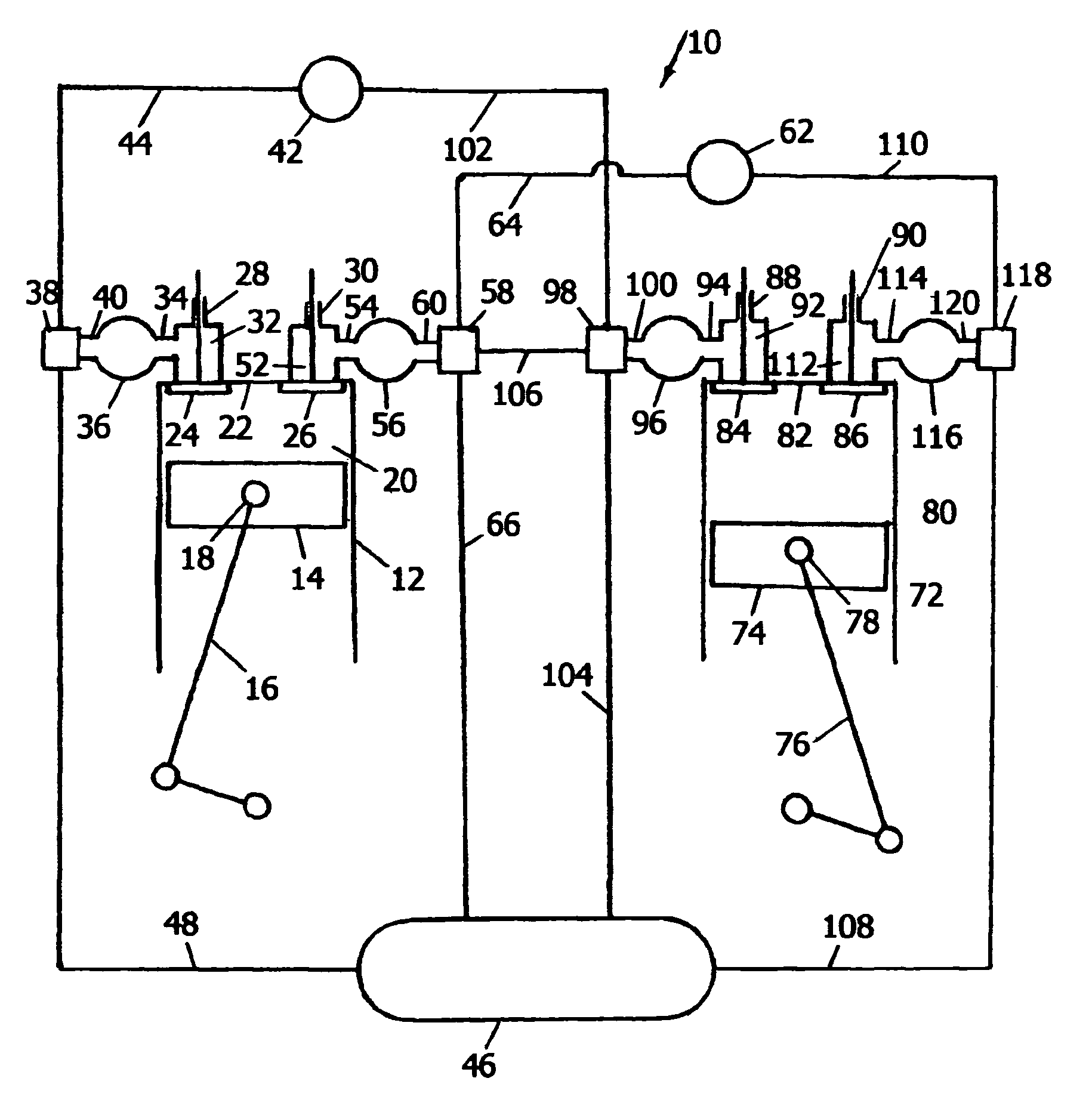
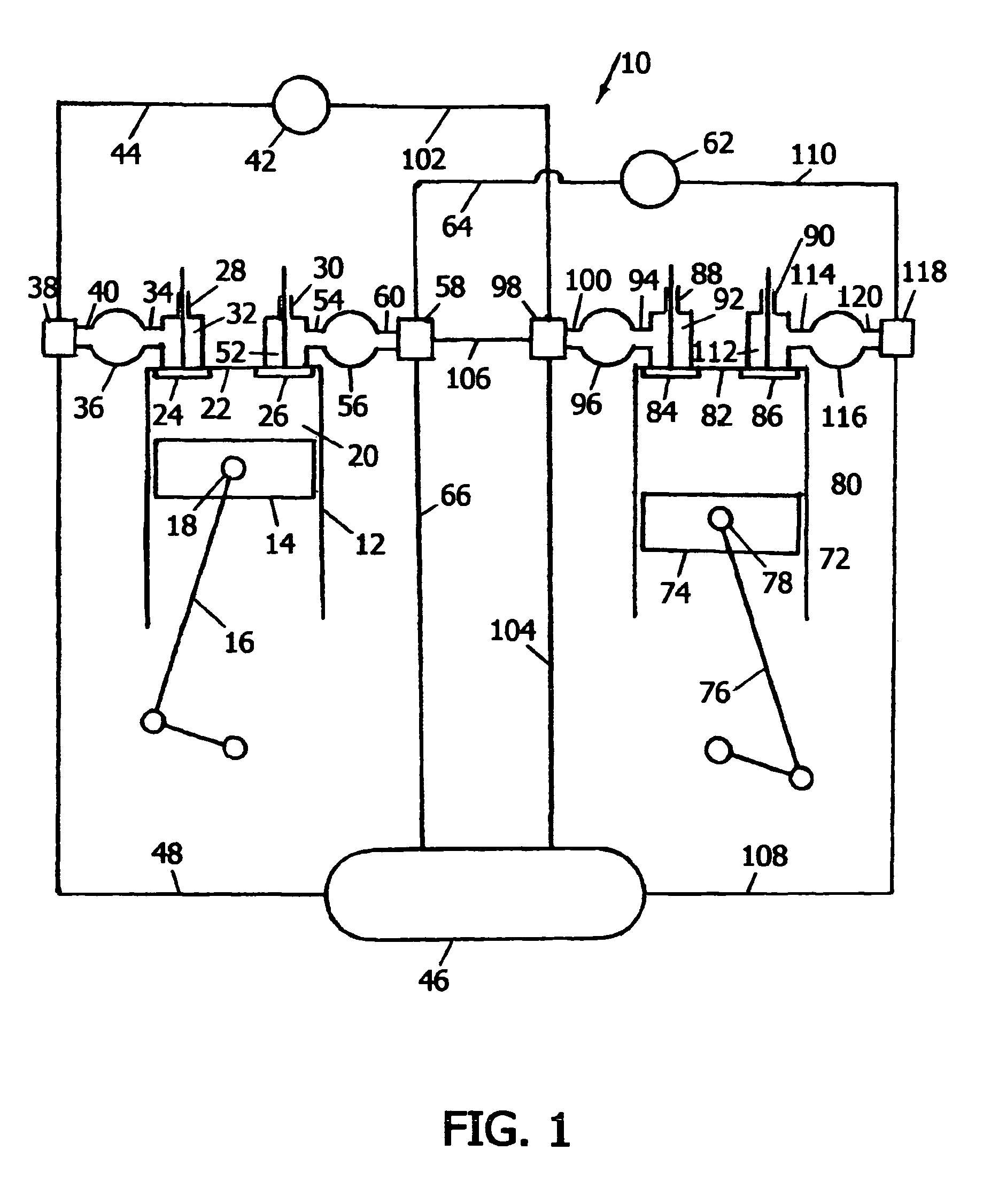
[0102]A preferred embodiment of the present invention is illustrated in FIGS. 1 to 5A and 5B. FIG. 1 is a schematic, cross-sectional side-view of two engine cylinders and their gas-flow connections to outside atmosphere, to compressed-air reservoir, and to each other. An engine 10 has at least two cylinders, including at least one primary cylinder 12 and at least one secondary cylinder 72. The design of the primary and secondary cylinders is identical, but they may perform different functions, depending on the mode of the engine operation.

[0103]Primary cylinder 12 contains a piston 14 that is mounted upon a connecting rod 16 by a wrist pin 18 and can reciprocate in cylinder 12, thus varying the volume of a cylinder chamber 20 enclosed between piston 14 and a cylinder head 22 attached to the top of cylinder 12. There are two types of normally-closed valves in cylinder 12, a first valve 24 and a second valve 26. Valves 24 and 26 are installed in cylinder head 22 an...


PUM


Abstract

High vehicle fuel efficiency is achieved by reducing fuel consumption during driving both in the city and on the highway. During driving in the city, the system accumulates the energy derived from vehicle motion during braking, and uses it to assist in vehicle propulsion at a later time. The energy can be stored either in a compressed-air reservoir or in an electric battery. During cruising on the highway, the engine operates in a two-stage gas-expansion cycle. The engine has primary and secondary cylinders. Only primary cylinders operate in internal-combustion mode. After expansion in primary cylinders, combustion gas is subjected to a second stage of expansion in secondary cylinders. This substantially improves the engine efficiency. Whenever heavy engine load is needed, all cylinders operate in internal-combustion mode.

Description

CROSS-REFERENCE TO RELATED APPLICATIONS[0001]application Ser. No. 10 / 822,448. Filing Date: Apr. 9, 2004FEDERALLY SPONSORED RESEARCH[0002]Not applicableSEQUENCE LISTING OR PROGRAM[0003]Not applicableFIELD OF THE INVENTION[0004]The present invention relates to vehicle systems capable to accumulate energy derived from vehicle motion during its deceleration or obtained from operation of the vehicle engine, and use the accumulated energy to assist in vehicle acceleration and propulsion at a later time. It also relates to systems that extract additional energy from the engine exhaust gas, and use that energy to reduce the vehicle fuel consumption.BACKGROUND OF THE INVENTION[0005]Most automotive vehicles are propelled by internal combustion-engines consuming hydrocarbon fuels. Burning these fuels produces exhaust gas containing harmful air pollutants, such as carbon monoxide, nitrogen oxides, and unburned hydrocarbons. It also contains substantial amount of carbon dioxide which, if produce...

Claims


Application Information

Patent Timeline
IPC IPC(8): B60L11/16B62M1/10F02B19/00B60L50/30
CPCB60K6/12B60K6/365B60K6/48B60L11/14B60L11/16B60W10/06B60W10/08B60W20/00B60K6/24B60L2200/26B60L2240/423B60L2240/662B60W2550/12B60W2710/0666B60W2710/083F02B61/045Y02T10/6221Y02T10/6286Y02T10/6295Y02T10/642Y02T10/7077Y02T10/7291Y02T90/16Y02T10/70B60L50/16B60L50/30B60W2555/20Y02T10/62Y02T10/64Y02T10/72Y02T10/7072B60W20/13
Inventor SCHECHTER, MICHAEL MOSES
Owner SCHECHTER MICHAEL MOSES
Learn More