Self-healing cutting apparatus and other self-healing machinery

a cutting apparatus and self-healing technology, applied in the field of machines, can solve the problems of many known cutting systems being prone to wear and failure, and none of the current known and used systems are capable of completely destroying a document or other sensitive material into an information-unrecoverable form using a simple method, and achieve the effect of reducing vibrations caused during a cutting procedure and simple spring-driven pressur

Active Publication Date: 2009-10-27
CASTRONOVO CHARLES A
View PDF26 Cites 11 Cited by
  • Summary
  • Abstract
  • Description
  • Claims
  • Application Information

AI Technical Summary

Benefits of technology

[0038]Additionally, in another preferred embodiment, the invention provides a method of protecting a cutter longevity and / or achieving zero-clearance cutting, comprising: sacrificing at least one solid blade bed or round bar against a cutter, wherein the blade bed is (a) relatively softer than the cutter and (b) relatively harder than an object or a material being destroyed by the cutter.
[0040]The positively-controlled material feed mechanism may control particle size of the material being destroyed by controlling both (a) the feed rate of the material entering between the at least one sacrificial blade or round bar and the at least one cutter and (b) the rotational speed of the at least one cutter.
[0043]When a rotary cutter is used, the arrangement may be that at least one tooth of the rotary cutter grabs the material prior to the material being metered into the zero clearance portion. It may be provided for the combination of the rotary cutter and the sacrificial blade or round bar to cut the material into the fiber or powder form. There may be included a mechanism adapted to ensure the at least one sacrificial plate or round bar is in contact with the cutting blade during a rotation of the cutting blade. There may be included a pressure plate contacting the sacrificial plate or round bar, the pressure plate adapted to at least maintain a position of the sacrificial plate or round bar with respect to the cutting blade and substantially eliminating vibrations caused during a cutting procedure. There may be included a mechanism coupled to the pressure plate for providing pressure to the pressure plate. The pressure plate may be of such material density and size as to provide inertial damping of vibrations, in addition to simple spring-driven pressure.

Problems solved by technology

However, none of the currently known and used systems are capable of completely destroying a document or other sensitive material into an information-unrecoverable form using a simple “one-step” cutting approach.
Existing document-destruction machines are intricate, complex, and delicate.
This poses a problem in high security applications, such as highly sensitive or classified government documents that need to be easily and efficiently destroyed for various security or business reasons.
Also, many of the known cutting systems are prone to wear, failure and other problems which require constant maintenance and / or refurbishment.
The maintenance and / or refurbishment of these complex systems, of course, requires considerable “down-time” which, in turn, also adds to the overall costs of the system.
In this system, a paper document is capable of being ground to a powder form; however, this system uses both a complex arrangement consisting of a corrugation system and an impacting or pulverizing system.
In this system, if one of the components fails, for example, the corrugation system, then the document cannot be pulverized.
This may result in a significant security risk.
This may lead to additional (i) component failure, (ii) maintenance and (iii) downtime, thereby increasing the cost of the entire system.
Also, in the pulverizing step, it is necessary to repeatedly pulverize the material over an extended time period in order to achieve the powder form, thus resulting in a disadvantage of the system.
This is a limiting feature of the Jang apparatus.
In this shredder, a shredding knife simply shreds paper; however, this system does not and, in fact, appears to be incapable of completely shredding paper into an information-unrecoverable product.
Also, this same system seems applicable only to paper products, thus limiting its applicability to other products (such as polyester (“Mylar”) tape) which require shredding or destruction.
Similarly, U.S. Pat. No. 5,320,287 to Li also shows a paper shredder which is provided for the limited use on paper, and which also is incapable of providing an information-unrecoverable product.
Of course other materials may also be destroyed for high security purposes.
Such materials may also need to be destroyed in a high security fashion.
Conventionally, this could heretofore only be performed by high-security document “disintegrators”, which are heavy (several hundred pounds), expensive, power-hungry, and very noisy.
Conventional shredding machines, including “disintegrators”, tend to jam with such materials (like Mylar), which tend to stretch and spindle, rather than be cut properly by the shredding or “disintegrating” apparatus.
Existing “high-security disintegrators” have the further disadvantage of limited effectiveness, in that the current Department of Defense standard for such machines specifies a 3 / 32″ output screen.
Such films or film-containing papers could, of course, be destroyed by incineration, but this method is undesirable for reasons of health (toxic fumes from burning), convenience, and secrecy.
However, eventually the sharp edges get worn off, blunted, and ground away.
Such an apparatus gets dull because the action of parts rubbing against each other wears away the material of each.
Zero-tolerance between parts can be kept by using spring-loading but such an arrangement is not actually cutting but rather is bludgeoning and takes more power than cutting.
Non-helically fluted shapes do not provide the cross-cut, but only the strip-cut.
Strip-cutting cannot reduce the output to a size as small as desired, because the there is a limit to how thin the cutters can be made, which in turn limits how thin the resulting strips can be.
However, that device has these limitations (among others): 1) Multiple heads are needed to sequentially re-shred the material.
This requires a costly and complex machine.
The cutting elements must therefore be somewhat delicate, which leads to shorter overall cutter life, greatly reduced reliability, and greatly increased susceptibility to damage from the introduction of staples, paper clips, etc. into the shredding process along with the paper.
This is a problem for all high-security shredders, and the finer the output, the greater the problem.
3) Even with multiple heads, there is a possibility of oversized particles getting past all of the heads.
Such conventional scissoring action, multi-head machines suffer from inherent limitations both through machining tolerances and through the impossibility, at a certain point even if a smaller parts can be made, of providing support for the reduced-size parts, and providing force to shred the paper without bending or breaking the delicate shredder parts.
Adding to the concerns and problems discussed above for paper and paper-like products, there is further considered the problems, perhaps even more technically complex, of destroying information stored on or in other media besides paper.

Method used


Image

  • Self-healing cutting apparatus and other self-healing machinery
  • Self-healing cutting apparatus and other self-healing machinery
  • Self-healing cutting apparatus and other self-healing machinery

Examples


example 1

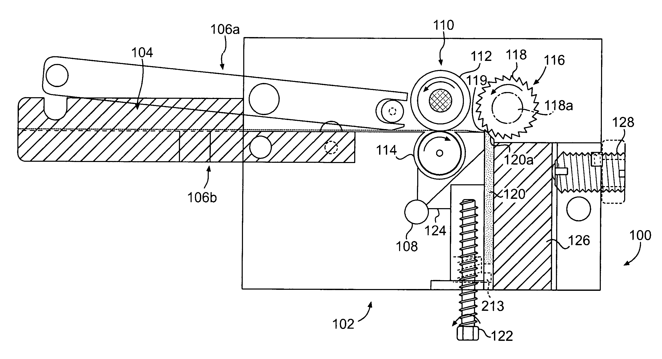
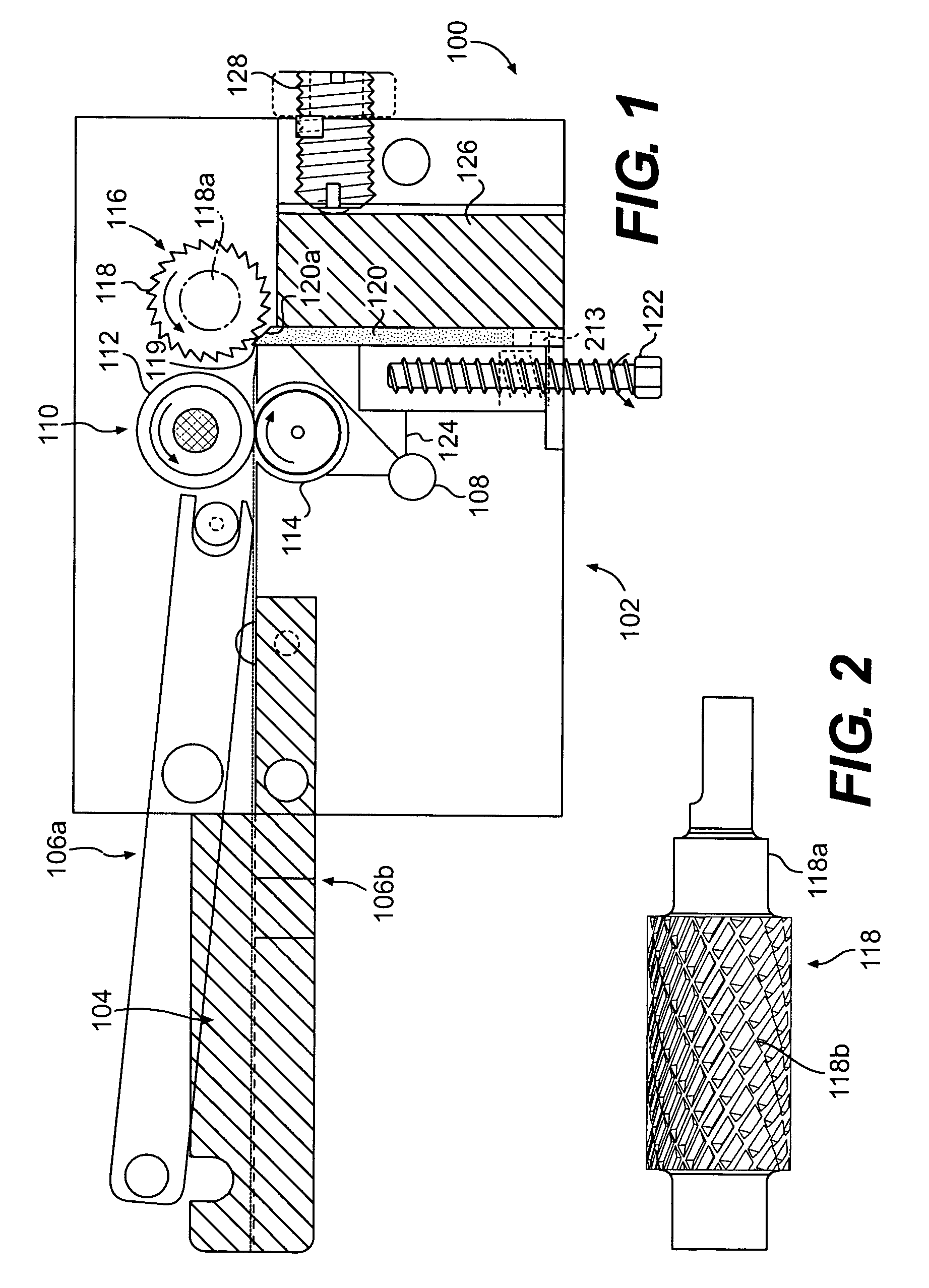
[0153]A prototype machine (and, subsequently, a production machine) was built, Model KD-100 (Key Tape Disintegrator), one instance of the more general class of machines which the present inventor calls “Micro-Disintegrators”. This class of machines is so named for two principle reasons: 1) Because the machines are physically small, considering their function, 2) The output (or “residue”, as it is designated in the art) produced by such machines is composed of extremely small dust-like particles, similar to those from a disintegrator, but finer. The actual KD-100 resembles that depicted in FIG. 1.

[0154]It utilizes only a single motor which performs all four of these functions: a) drives the cutter; b) drives the vacuum dust collection system; c) drives the positively-controlled material capstan feed (through gear trains); d) drives the extremely slow and gradual upwards motion of the sacrifice plate (through an additional gear train). The actual machine is in full compliance with Dep...

example 2

Round-Bar Sacrifice Material

[0156]In this example there is assumed a round sacrifice bar ⅜″ diameter, or 1.17″ circumference. A full revolution of the bar would present 1.178 million micro-inches to the cutter. At about 13 ft / minute, the sacrifice feed would be 30×13 (or 390) micro-inches circumferentially per minute, which works out to 390 / 1,178,000 (or 0.000331) sacrifice bar revolutions per minute, or 0.0198 (or 1 / 50.34) sacrifice bar revolutions per hour. The bar will last about 50 hours, or 46,800 feet. In this case, a feed rate of approximately 30 micro-inches of sacrifice material per foot length of destroyed material, or about 400,000 inches of destroyed material per inch of sacrifice material is provided, for this round-bar sacrifice material example.

[0157]This may be compared to about 0.500 sacrifice JACKSCREW revolutions per HOUR in a sacrifice PLATE embodiment. Correspondingly, more worm-gear drive ratio reductions are needed to operate with the round bar.

example 3

DocuStroyer / CRYPTOSTROYER Paper-Destruction Machine

[0158]A destruction machine for to-be-destroyed 8½ inch-wide paper was constructed according to FIGS. 12A-12D. A cutter was made from cobalt steel, coated with titanium nitrate (to enhance its hardness). A cutter as in FIG. 11 was used. The cutter had raised cutting edges with vertical serrations, with a 0.007 inch offset pattern to the serrations. A 9-inch wide sacrifice material of 3 / 16 inch thick soft aluminum was used. A destruction machine for 8½ inch wide paper was constructed as described above with regard to FIGS. 11-12D.

[0159]The inventive DocuStroyer / CRYPTOSTROYER machine was tested on 10 paper pages in rapid sequence, fed one at a time (generating 10 end-strips). The end-of-page strip processed through the secondary shredder. All that remained of the 10 paper pages was powdery dust.

[0160]In addition to the excellent destruction capability provided by the DocuStroyer / CRYPTOSTROYER device of this example, the inventive mach...


PUM


Abstract

Self-healing of a mechanical part in a mechanical system is provided, such as a self-healing part in a cutting apparatus. Differential hardness of respective parts in contact with each other is used. Undesirable damage from a foreign object in a mechanical system is managed by directing damage away from a part that is not wanted to be damaged and towards a part that may receive damage and be replaced. True zero-clearance cutting on a commercial scale is provided via a cutting area including a sacrifice material that is relatively softer than the cutter. One example is a cutting system which is capable of cutting a material such as, for example, tape or paper, into a fiber or powder. Destruction of the material is further enhanced by advantageous strategic patterning of cutting edges on a rotary cutter, and further by secondary shredding features. For example, on the same axis as the rotary cutter, may be disposed, one on each end, rotating secondary shredders that receive material that has been cut by the rotary cutter as well as material that has escaped cutting by the rotary cutter. A variety of materials, of different thicknesses and types, may be reduced to a dust or powder-size. A single destruction machine advantageously may receive (with minimal operator intervention) a mixed input load, such as a mixture of a combination of paper (including paper that is folded, ripped, stapled, or otherwise irregular), CDs, DVDs, polyester, plastic cards, SMART cards, wood, Verichips, flash drives, biometric chips, and / or other generally-planar materials.

Description

RELATED APPLICATIONS[0001]This is a continuation in-part of application Ser. No. 10 / 951,924 filed Sept. 29, 2004, now U.S. Pat. No. 7,111,801 which is a continuation-in-part of application Ser. No. 10 / 228,085, filed Aug. 27, 2002, now U.S. Pat. No 6,938,844 which claims benefit of U.S. provisional application Ser. No. 60 / 342,111 filed Dec. 26, 2001.FIELD OF THE INVENTION[0002]The present invention generally relates to machinery, more particularly, to cutting systems and, more particularly, to cutting systems capable of reducing material to either a shredded form or an unrecoverable fiber or powder form. Also, the present invention generally relates to cutting very thin materials, including very thin materials alone (such as paper, etc.) and very thin materials present with other components (such as a credit card, data card, compact disk, floppy disk, cassette tape, etc.); thick materials also may be cut. Non-homogeneous input loads may be cut.BACKGROUND[0003]There are many types of ...

Claims


Application Information

Patent Timeline
Patent Type & Authority Patents(United States)
IPC IPC(8): B02C18/16B02C18/00B02C18/18B02C18/22
CPCB02C18/0007B02C18/148B02C18/16B02C18/18B02C18/2283B02C2018/2208B02C2018/0015B02C2018/168B02C2018/188B29B9/04B26D7/26
Inventor CASTRONOVO, CHARLES A.
Owner CASTRONOVO CHARLES A
Why Eureka
Try Eureka