Halogenated solvent remediation

a technology of halogenated solvents and solvents, applied in the field of environmental pollution remediation, can solve the problems of infiltration of groundwater supplies, contaminated areas containing relatively high concentrations of contaminants, and little care in the handling of organic solvents and other materials used in industry and at government installations, and achieve the effects of enhancing in situ bioremediation, enhancing mass transfer of nonaqueous halogenated solvents, and enhancing bioremediation

Inactive Publication Date: 2008-11-11
SRP TECH
View PDF29 Cites 5 Cited by
  • Summary
  • Abstract
  • Description
  • Claims
  • Application Information

AI Technical Summary

Benefits of technology

[0015]It is a feature of the present invention to provide a method for in situ remediation of DNAPLs in ground water wherein capital costs are low.
[0016]It is also a feature of the invention to provide a method for in situ remediation of DNAPLs in ground water wherein mass transfer from the nonaqueous phase to the aqueous phase is enhanced.
[0017]It is another feature of the invention to provide a method for in situ remediation of DNAPLs in ground water wherein the longevity of source areas is shortened.

Problems solved by technology

For many years little care was taken in the handling of organic solvents and other materials that were used in industry and at government installations, such as military bases.
Because of poor handling techniques and, occasionally, intentional dumping, many industrial sites and military bases now have contaminated areas containing relatively high concentrations of these contaminants.
Chlorinated solvents, such as trichloroethylene (TCE), perchloroethylene (PCE), and other types of liquids, are common at such sites, and if not removed can infiltrate groundwater supplies, rendering the water unfit for consumption and other uses.
Because of the low aqueous solubility of most DNAPLs, their removal by ground water extraction requires exceptionally long periods of time.
A serious drawback with the surfactant-enhanced aquifer remediation is that the vertical mobility of the solubilized DNAPLs substantially requires that an aquiclude be present to catch any solubilized contaminant that migrates vertically.
Many aquifers, however, lack such an aquiclude.
If the traditional surfactant-enhanced aquifer remediation method were to be used with an aquifer lacking an aquiclude, there is a significant risk that the solubilized DNAPLs will spread vertically and contaminate an increasingly large volume.
Another drawback of surfactant-enhanced aquifer remediation is the need to pump high concentrations of contaminated water above ground, which results in exposure risks to workers and the environment, and the need to dispose or recycle the surfactant.
The utilization of an appropriate carbon source induces an enzyme that fortuitously degrades many halogenated solvents, but without any immediate benefit to the microorganisms involved.
Consequently, bioremediation is not generally thought to be applicable to sites with residual DNAPLs in the subsurface.
At many sites, however, the pump-and-treat process continues to be used to hydraulically contain residual source areas although it is almost universally accepted that these systems will have to operate in perpetuity because of their inefficient removal of nonaqueous contaminants.

Method used


Image

  • Halogenated solvent remediation
  • Halogenated solvent remediation
  • Halogenated solvent remediation

Examples


example 1

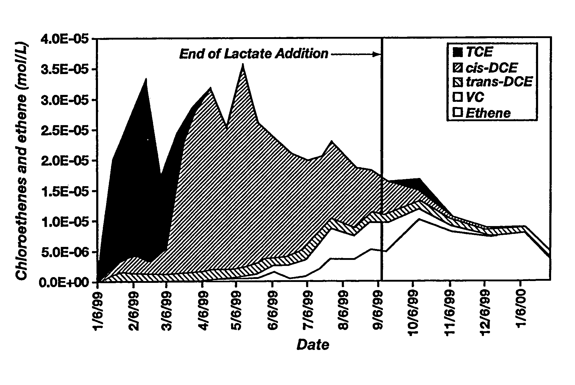
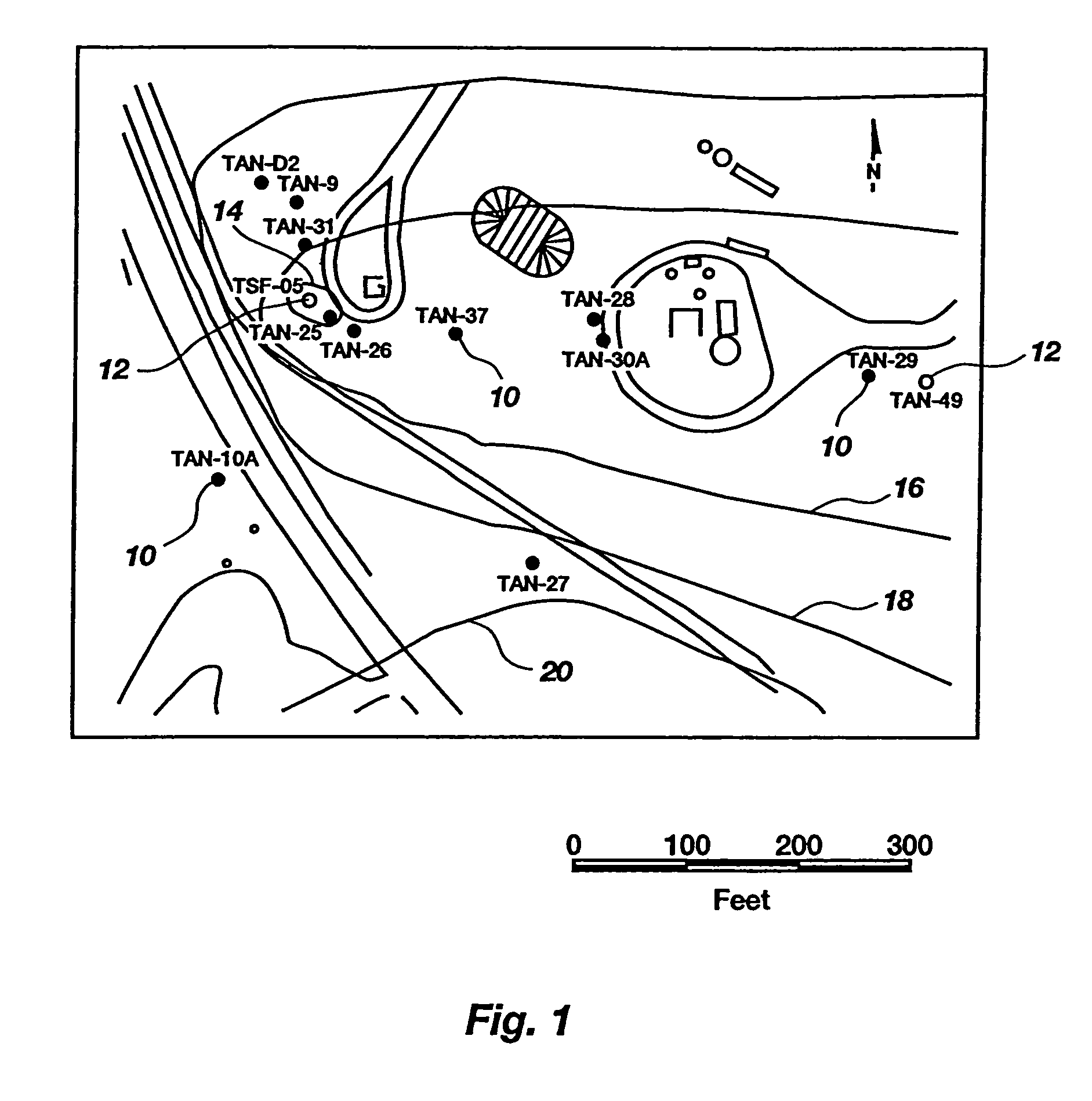
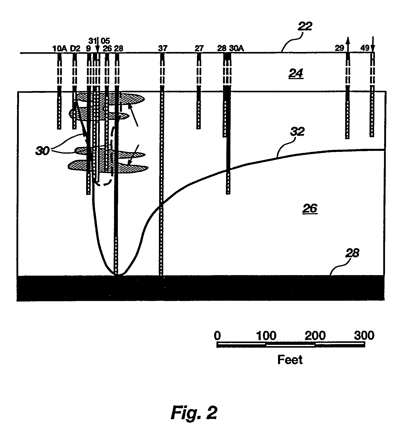
[0073]A 1-year field evaluation of enhanced in situ bioremediation was performed at Test Area North (“TAN”) of the Idaho National Engineering and Environmental Laboratory. FIG. 1 shows a site plan of TAN, wherein solid symbols represent monitoring wells (10) and open symbols represent injection wells (12). The locations of a 5,000 μg / L TCE isopleth (14); 1,000 μg / L TCE isopleth (16); 100 μg / L TCE isopleth (18); and 5 μg / L TCE isopleth (20) are shown by solid lines. FIG. 2 illustrates a cross section of this site, showing the surface of the ground (22), an approximately 63-m (210-feet) fractured basalt unsaturation zone (24) (not drawn to scale), an approximately 60-m (200-feet) fractured basalt aquifer (26), and an impermeable clay interbed (28). The approximate location of the TCE secondary source (30) and the 1,000 μg / L TCE isopleth (32) are also indicated. The test was performed to determine whether this technology has the potential to enhance or replace the default pump-and-trea...

example 2

[0085]Based on the field results presented in Example 1, laboratory studies were performed to confirm that the enhanced bioavailability of TCE observed in the field was due to co-solvent or surfactant behavior resulting from the use of high concentrations of sodium lactate. Two fundamental properties used to screen the co-solvent or surfactant properties of a solution are surface tension and interfacial tension. Surface tension measures the force per unit length along the interface between a liquid and air due to its tension. When a co-solvent or surfactant is present in an aqueous liquid at increasing concentrations, the surface tension of that liquid decreases. Interfacial tension is similar to surface tension except that it measures the force per unit length along the interface between two liquid phases arising from the surface free energy. The higher the interfacial tension between two liquids, the less likely one is to dissolve into the other, and the more difficult it is for o...

example 3

[0091]Site Background. A site-wide Remedial Investigation (RI) identified a chlorinated solvent plume in a sandy aquifer approximately 35 to 60 feet (10.7 to 18.3 m) below ground surface at the 164th Airlift Wing at the Tennessee Air National Guard Site, Memphis, Tenn. The plume area targeted for treatment was over 2 acres (0.81 hectares). This unconfined saturated interval is overlain by an inorganic loess vadose zone and is separated from the deeper regional aquifer by a clay unit. PCE concentrations ranged from 5 to 1,000 μg / L in the target area, while TCE ranged from 100 to greater than 15,000 μg / L in the injection / monitoring wells. The aquifer initially exhibited conditions ranging from aerobic to mildly reducing. A pilot test of a sodium lactate injection system to enhance natural reductive dechlorination in the groundwater was approved by the Tennessee Department of Environment and Conservation, the Memphis and Shelby County Health Department, and the Shelby County Ground Wat...


PUM

PropertyMeasurementUnit
diameteraaaaaaaaaa
diameteraaaaaaaaaa
thickaaaaaaaaaa

Abstract

Methods for enhancing bioremediation of ground water contaminated with nonaqueous halogenated solvents are disclosed. An illustrative method includes adding an electron donor for microbe-mediated anaerobic reductive dehalogenation of the halogenated solvents, which electron donor enhances mass transfer of the halogenated solvents from residual source areas into the aqueous phase of the ground water. Illustrative electron donors include C2-C4 carboxylic acids and hydroxy acids, salts thereof, esters of C2-C4 carboxylic acids and hydroxy acids, and mixtures thereof, of which lactic acid, salts of lactic acid—such as sodium lactate, lactate esters, and mixtures thereof are particularly illustrative. The microbes are either indigenous to the ground water, or such microbes can be added to the ground water in addition to the electron donor.

Description

CROSS-REFERENCE TO RELATED APPLICATIONS[0001]This application is a continuation-in-part of U.S. application Ser. No. 09 / 895,430, filed Jun. 29, 2001, now U.S. Pat. No. 6,783,678, which claims the benefit of U.S. Provisional Application No. 60 / 214,957, filed Jun. 29, 2000, and U.S. Provisional Application No. 60 / 233,414, filed Sep. 18, 2000, which are hereby incorporated by reference.STATEMENT REGARDING FEDERALLY SPONSORED RESEARCH OR DEVELOPMENT[0002]This invention was made with United States Government support under Contract No. DE-AC07-99ID13727 awarded by the United States Department of Energy. The United States Government has certain rights in the invention.BACKGROUND OF THE INVENTION[0003]This invention relates to remediation of environmental contamination. More particularly, the invention relates to methods for accelerating or enhancing in situ dehalogenation of nonaqueous halogenated solvents in ground water. These methods involve adding to the contaminated ground water a com...

Claims


Application Information

Patent Timeline
Patent Type & Authority Patents(United States)
IPC IPC(8): C02F3/00B09C1/00B09C1/10
CPCB09C1/002B09C1/10
Inventor SORENSON, JR., KENT S.
Owner SRP TECH
Why Eureka
Try Eureka