Method and system for coating sections of internal surfaces

a technology of internal surface and coating section, applied in the direction of vacuum evaporation coating, solid-state diffusion coating, mechanical equipment, etc., can solve the problems of multiple ionizing collisions, increased coating time, and inability to use heat-sensitive substrates with thermal techniques, so as to reduce the total coating time, improve uniformity, and increase the length of the section

Active Publication Date: 2009-10-27
AGM CONTAINER CONTROLS
View PDF19 Cites 52 Cited by
  • Summary
  • Abstract
  • Description
  • Claims
  • Application Information

AI Technical Summary

Benefits of technology

[0009]A method in accordance with the present invention allows uniform coating of internal surfaces of a long pipe, tube or other workpiece by isolating smaller sections of the pipe and then using the pipe section itself as a deposition chamber. The method includes isolating the section of pipe to be coated by inserting solid plates through the openings of the workpiece and locating them at each end of the section to be coated, coupling a first plate of the pipe section to a gas supply subsystem to function as an entrance, and coupling a second plate of the pipe to a pumping subsystem to function as the exit. Gas is flowed through the pipe section from the first isolating plate (entrance) to the second isolating plate (exit). This source gas can be activated to coat the surface of the workpiece by either thermal or plasma methods or a combination of the two. Using thermal methods, the workpiece can be placed in a heated oven or it can be wrapped in an insulating blanket with a heating coil without the need for a furnace. Thermal techniques can only be used for substrates that are not heat sensitive. For heat-sensitive workpieces, some amount of plasma activation or PECVD must be used to lower the required activation temperature.
[0012]For the PECVD application of the sectional coating process, the gas flow and the pumping speed preferably are adjusted such that the pressure provides a hollow cathode environment in the workpiece upon application of a voltage bias. This pressure is such that the electron mean free path is slightly less than the diameter of the tube, causing electrons to oscillate across the tube and resulting in multiple ionizing collisions and a more intense plasma. This provides an improvement relative to prior art PECVD approaches in which plasma is generated externally from a workpiece, resulting in a loss of ionization as gas flows through the tube, so that less film deposition occurs toward the exit from the workpiece. In comparison, as a consequence of the hollow cathode generated throughout the pipe section, the invention achieves a more uniformly ionized plasma along the length of the section, thereby providing a more uniform deposition.
[0013]The sectional coating method provides an improvement relative to prior art CVD approaches in which precursor gas is flowed from the entrance of a high aspect ratio workpiece to the exit, resulting in a loss of precursor gas concentration as the gas flows through the tube. Using these prior art approaches, the gas reacts initially at the entrance, leaving a smaller concentration of precursor gas toward the exit. By-product gas species can also be formed, further diluting the reactant gas, so that less film deposition occurs toward the exit from the workpiece. This is commonly referred to as “depletion” of the precursor gas. This depletion problem will become more severe for long lengths and small diameters. In comparison, as a consequence of the sectional coating, the invention eliminates depletion by enabling the coating of smaller sectional lengths, thereby providing a more uniform deposition.
[0014]The method allows coating of interior surfaces of pipes, tubes, valves, pumps or other workpieces with more complex geometries. The sectional coating significantly reduces the possibility of an end-to-end decline in coating thickness as a consequence of a gradual reduction of the density of coating material in the plasma as the coating material is drawn from the plasma to the internal surface or surfaces of the workpiece.
[0018]In other embodiments, the biasing system may be a pulsed DC bias voltage. A negative pulsed DC voltage is applied to have a duty cycle that is selected such that (1) when the voltage is “on,” a negative voltage is applied to the workpiece such that positive source gas ions are attracted to the internal surfaces and react chemically to coat the internal surfaces of the workpiece, and (2) when the voltage is “off,” the positive source gas ions are sufficiently replenished within the interior of the workpiece to provide uniformity in coating the internal surfaces. If the coating material is an insulator, the “off” condition of the duty cycle may include a reverse voltage that is sufficient to deplete surface charges resulting from the coating of the internal surfaces of the workpiece.
[0020]In another embodiment of the invention, “flow-cycling” is used to further improve uniformity, or to increase the length of the section that may be coated, thus reducing total coating time. In this method, the gas supply and the pumping supply are coupled to both sectional plates and supplied with shutoff valves, so that gas can be either introduced or pumped out through either plate, as required. In a first coating cycle, gas is introduced through the “entrance” plate and is pumped out of the “exit” plate, and in a second cycle this flow is reversed in direction. The rate and the repetition of these cycles can be varied for different aspect ratio workpieces.

Problems solved by technology

Thermal techniques can only be used for substrates that are not heat sensitive.
This pressure is such that the electron mean free path is slightly less than the diameter of the tube, causing electrons to oscillate across the tube and resulting in multiple ionizing collisions and a more intense plasma.

Method used


Image

  • Method and system for coating sections of internal surfaces
  • Method and system for coating sections of internal surfaces
  • Method and system for coating sections of internal surfaces

Examples


Embodiment Construction

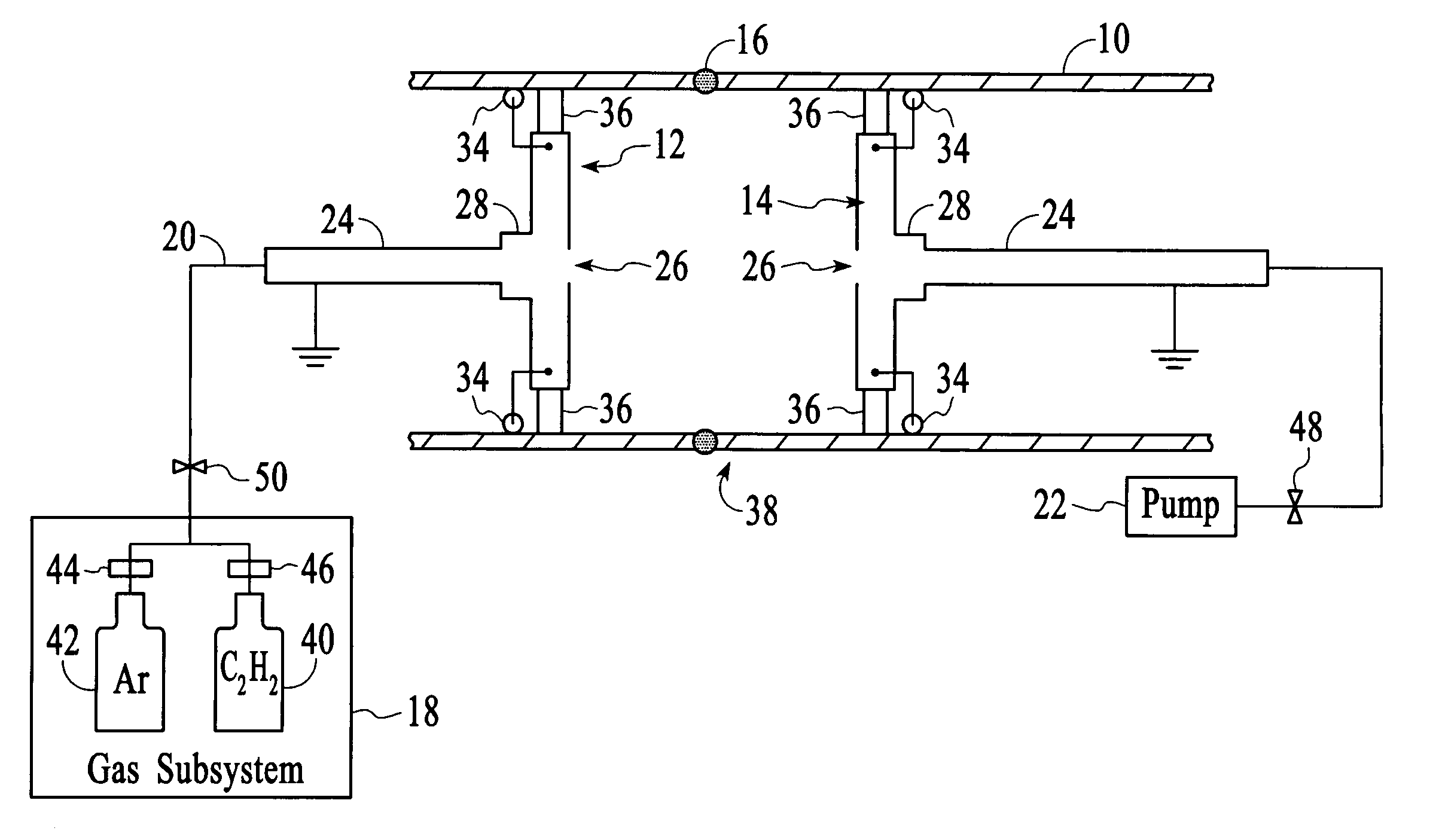
[0028]FIG. 1 shows a conductive workpiece 10 very long in length, for example having a length-to-diameter ratio greater than 50:1. The conductive workpiece may be an assembly of sections welded together to form long lengths of pipe, but may also be a single high aspect ratio piece. Often, sections of pipe, having already been coated and having a uniform coating, are welded together. The welds and the areas surrounding the welds, in which the welding process has compromised the coating, require corrosion-resistant coating.

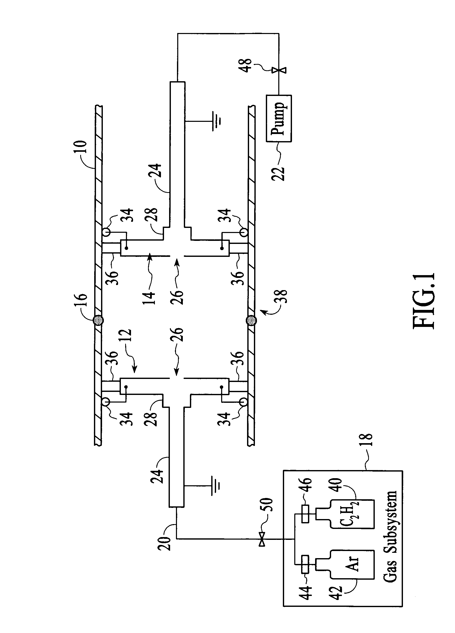
[0029]The conductive structures 12 and 14 are inserted into workpiece openings (not shown) and maneuvered into position at or near weld 16. The conductive structure 12 is coupled to a gas supply subsystem 18 via flexible gas supply line 20. The conductive structure 14 is coupled to a pumping subsystem 22via flexible pump lines 24. The gas supply and pump lines are connected to openings 26 (FIG. 2) by vacuum-tight fittings 28 by a means known in the art. The gas supp...


PUM

PropertyMeasurementUnit
aspect ratioaaaaaaaaaa
pressuresaaaaaaaaaa

Abstract

A method and system for coating the internal surfaces of a localized area or section of a workpiece is presented. Conductive structures are inserted into one or more openings of a workpiece to define the section to be coated. In some embodiments, a bias voltage is connected to a workpiece section, which functions as a cathode. A gas source and vacuum source are coupled to each conductive structure through a flow control system. The flow control system enables a first opening to function as a gas inlet and a second opening to function as a vacuum exhaust. Only the section encompassed by the conductive structures is coated. When the coating process is completed, a means for varying the conductive structures along the length is utilized to move onto the next section to be coated.

Description

TECHNICAL FIELD[0001]The invention relates generally to deposition systems and more specifically to methods and systems for coating pipes that are very long in length.BACKGROUND ART[0002]The corrosion of industrial piping and other components such as valves and pumps is a major problem in some industries. The oil industry, in particular, faces severely corrosive environments, with corrosive gasses and liquids such as H2S (hydrogen sulfide) at elevated temperatures and pressures. Additionally, these conditions form severe wear and erosion environments. One solution to these issues is to coat a lower grade base material with a high quality coating material having the desired high corrosion and wear-resistant properties. Typically, these types of properties will be found in metal, ceramic and particularly diamond-like carbon coatings.[0003]Expensive specialty alloys, such as Hastelloy and Inconel (both of which are federally registered trademarks of Huntington Alloys Corporation), are ...

Claims


Application Information

Patent Timeline
Patent Type & Authority Patents(United States)
IPC IPC(8): H01L21/00C23C14/00C23C16/00
CPCC23C16/0272C23C16/045C23C16/26C23C16/455F16L58/18F16L55/1645F16L58/02F16L58/04F16L58/1009C23C16/503
Inventor TUDHOPE, ANDREW WILLIAMBOARDMAN, WILLIAM JOHNMERCADO, RAUL DONATECONTRERAS, FREDERICK
Owner AGM CONTAINER CONTROLS
Why Eureka
Try Eureka