Rolling bearing for rocker arm

a technology for rolling bearings and rockers, which is applied in the direction of mechanical control devices, process and machine control, instruments, etc., can solve the problems of inability to smoothly control roller positions, insufficient lubricating conditions, and high labor intensity, and achieve excellent anti-secular-dimensional-change, excellent anti-crack strength, and remarkable improvement of rolling fatigue li

Active Publication Date: 2009-11-10
NTN CORP
View PDF44 Cites 20 Cited by
  • Summary
  • Abstract
  • Description
  • Claims
  • Application Information

AI Technical Summary

Benefits of technology

[0122]The rolling bearing for the rocker arm according to the first aspect of the present invention has austenite grains that are made fine to have a grain size number exceeding 10, and has a surface hardness Hv of at least 653. Therefore, the rolling fatigue life is remarkably improved, and an excellent anti-crack strength and an excellent anti-secular-dimensional-change can be achieved.
[0123]The rolling bearing for the rocker arm according to the second aspect of the present invention can have, under the conditions in use of an increased speed, an increased load and a decreased viscosity of a lubricating oil, a longer rolling fatigue life as well as a longer surface damage life depending on a surface damage due to metal contact.
[0124]The rolling bearing for the rocker arm according to the third aspect of the present invention can be made compact and prevented from shortening the life.
[0125]The rolling bearing for the rocker arm according to the fourth aspect of the present invention has austenite grains that are made fine to have a grain size number exceeding 10, and an area ratio of a spherical carbide of at least 10%, so that the rolling fatigue life is remarkably improved and thus excellent anti-crack strength and anti-secular-dimensional-change can be achieved.
[0126]The rolling bearing for the rocker arm according to the fifth aspect of the present invention has the hardened layer formed entirely in the radial direction from the rolling surface of the inner ring where rolling elements roll to the inner circumference, so that the static crack strength and the crack fatigue strength can be improved. Further, since the inner ring has a hollow cylindrical shape, the rolling bearing can be made lightweight and compact. Furthermore, the rolling bearing has the surface layer portion including the nitrogen-rich layer, has austenite crystal grains that are made fine to have a grain size number exceeding 10, has an appropriate amount of retained austenite, has an appropriate surface hardness, and has a high area ratio of the spherical carbide. Therefore, both of the usual load-dependent rolling fatigue life as well as the surface damage life depending on the metal contact due to sliding and missing oil film can be improved.

Problems solved by technology

In particular, regarding a full-type rolling bearing without cage, skew is likely to occur for the reasons that rollers interfere with each other and roller positions are not smoothly controlled.
Further, if a lubricating oil is not appropriately supplied into the bearing, an inadequate lubricating condition is likely to occur.
Thus, in spite of a large load-carrying capacity as calculated, surface damages (peeling, smearing, surface-originated peeling) and inside-originated peeling are likely to occur.
There is another problem regarding the rocker arm.
However, as for the downsizing of the bearing, because of limitations due to the shape of the cam and the lift amount in valve opening / closing, the size cannot be decreased simply and thus downsizing is chiefly done in the direction of the width (shaft).
Here, in making the bearing lightweight and compact, some issues have to be considered.
They are deterioration in crack fatigue strength of the outer ring or inner ring and shortening of the rolling fatigue life of the roller or inner ring.
However, this method imposes limitations on the shape, and thus hinders the bearing from being made lightweight and compact.
Further, for an inner ring having a simple hollow cylindrical shape, since the strength is insufficient due to the above-described reason, a reinforcing material may be attached to the inner circumferential portion (see Japanese Utility Model Laying-Open No. 3-063703 (Patent Document 19)).
This method, however, is accompanied by increased process steps and complexity, disadvantageously resulting in a higher price of the bearing.

Method used


Image

  • Rolling bearing for rocker arm
  • Rolling bearing for rocker arm
  • Rolling bearing for rocker arm

Examples


first embodiment

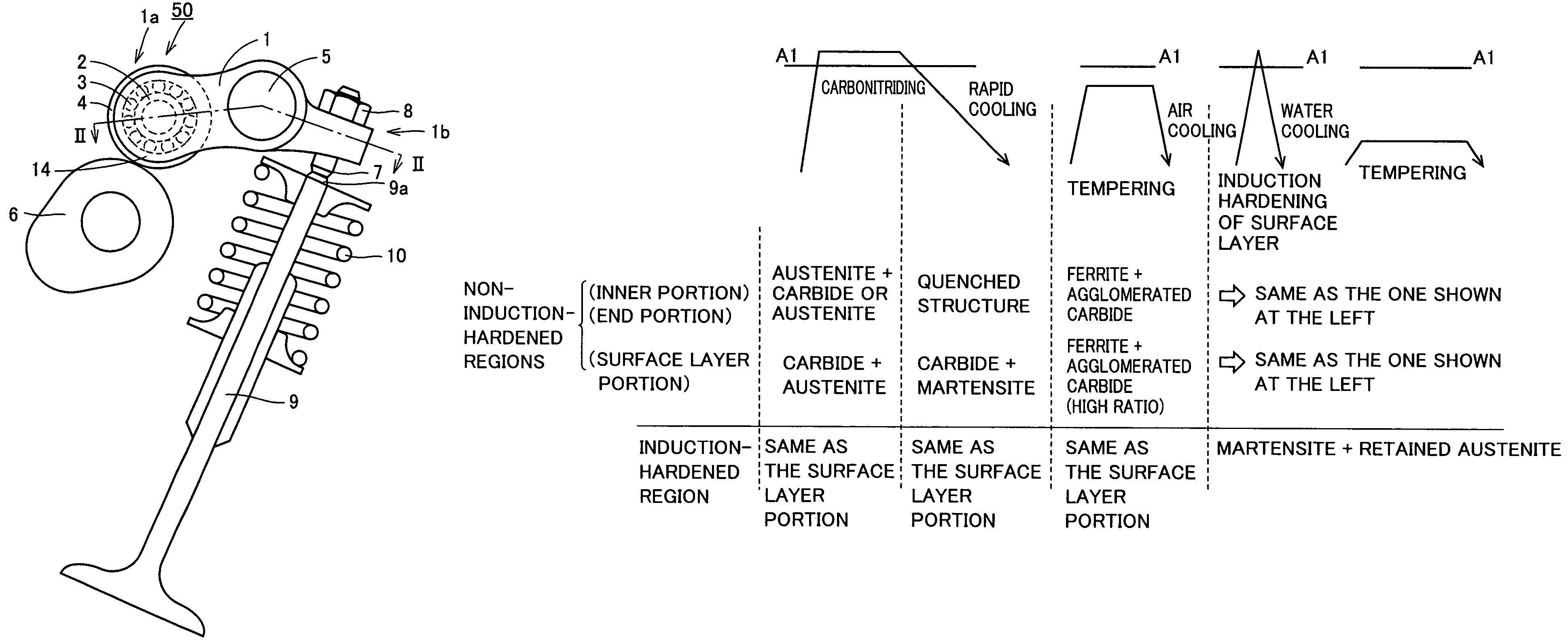
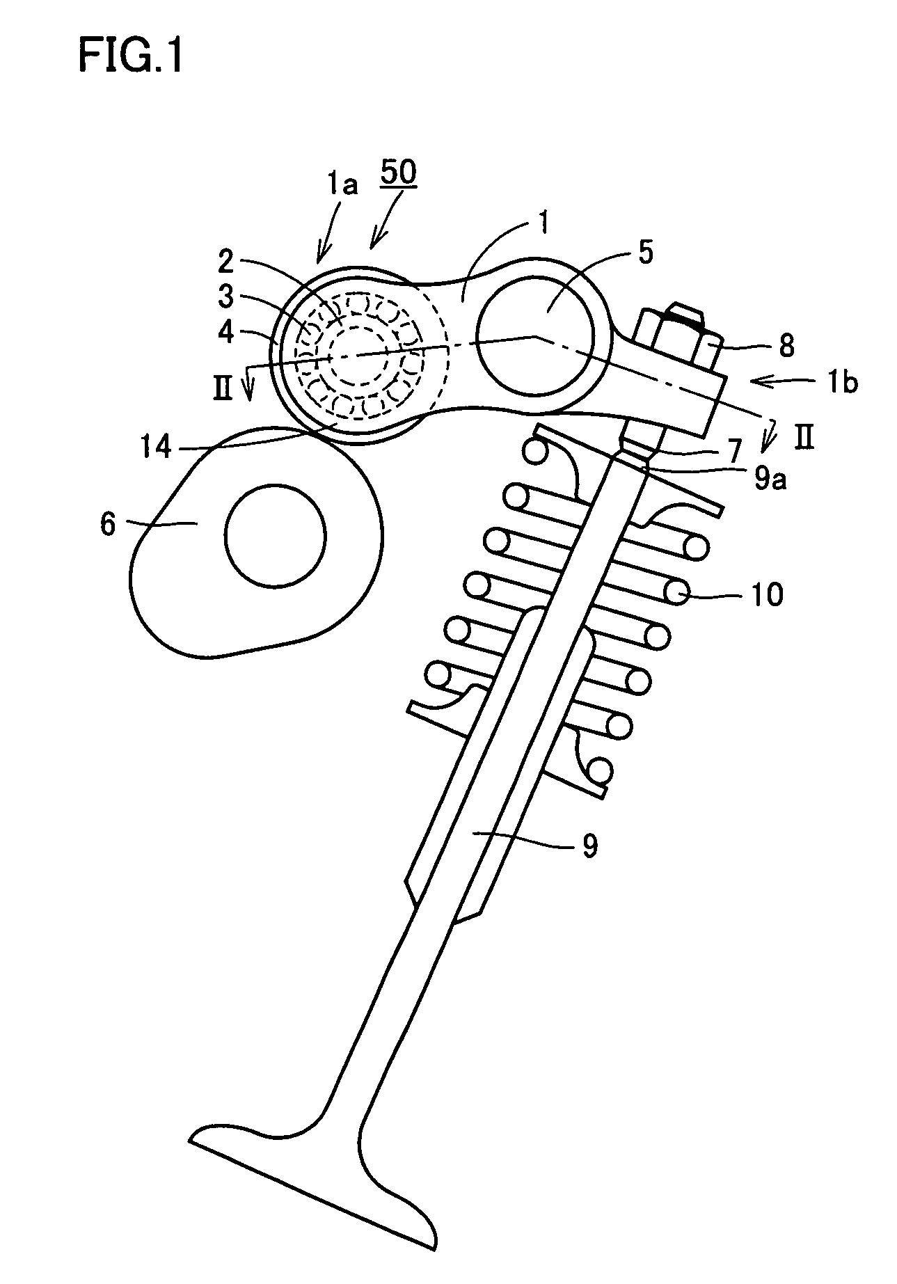
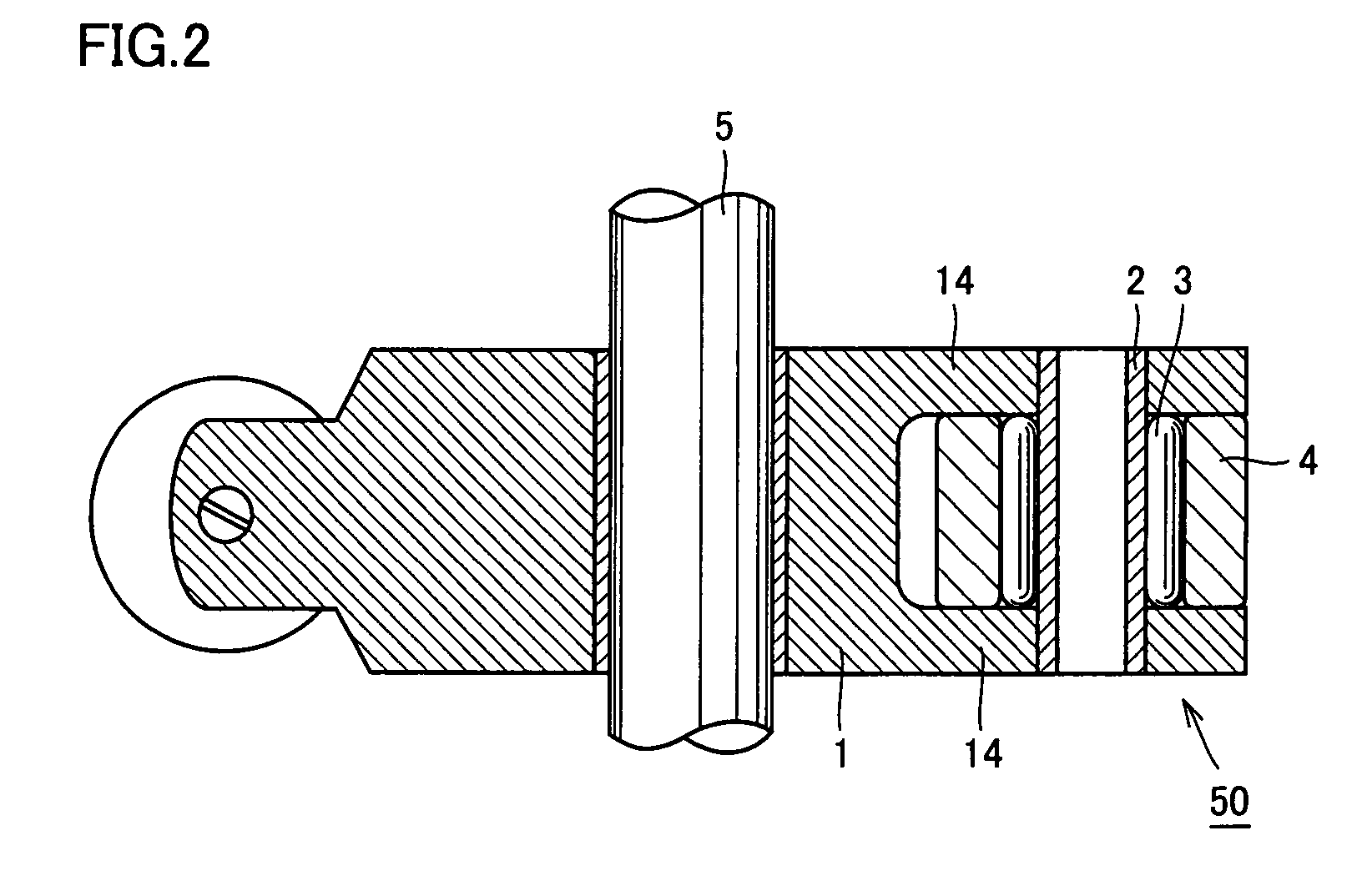
[0152]FIG. 1 is a schematic front view showing a rolling bearing for a rocker arm in use, according to a first embodiment of the present invention. FIG. 2 is a cross-sectional view along a line II-II in FIG. 1. Referring to FIGS. 1 and 2, rocker arm 1 that is a pivot member is pivotably supported, at a central portion located between one end 1a and the other end 1b, on a rocker arm shaft 5 via a bearing metal for example. Rocker arm 1 swings about rocker arm shaft 5.

[0153]Rocker arm 1 has one end 1b into which an adjust screw 7 is screwed. Adjust screw 7 is fastened by a lock nut 8 and has its lower end that abuts on an upper end 9a of an intake valve or exhaust valve of an internal combustion engine (open / close valve of an engine) 9. Valve 9 is biased by an elastic force of a spring 10.

[0154]Rocker arm 1 has the other end 1a where a bifurcated inner-ring support portion (outer-ring support portion) 14 is integrated. In an outer-ring shaft hole opened in this bifurcated inner-ring s...

second embodiment

[0171]Referring to FIGS. 1 to 5, inner ring 2 of rocker arm rolling bearing 50 in the present embodiment is made of a steel containing at least 0.50% by mass of carbon, has a hollow cylindrical shape and has a hardness of at least HV 200 and at most HV 300 at its end surface. Further, inner ring 2 of each rolling bearing 50 has, as shown in FIGS. 11(a), (b), a hardened layer extending entirely in the radial direction from a rolling surface of inner ring 2 where rollers (rolling elements) 3 roll to an inner circumferential surface 2c. Preferably, such a hardened layer is formed entirely in the circumferential direction of inner ring 2.

[0172]As a pattern of this hardened layer, Japanese Patent Laying-Open No. 2000-38906 discloses the one as shown in FIG. 10. Only a surface layer portion of the rolling surface of an outer circumferential surface 2b of inner ring 2 is a hardened layer 2a, and a surface layer portion of inner circumferential surface 2c and a surface layer portion of an e...

example 1

[0197]JIS standard SUJ2 was used to produce a rolling bearing for a rocker arm for use in a rolling fatigue test. The bearing was a full-type needle bearing used for a rocker arm. An inner ring had the size: outer diameter φ 14.64 mm×width L 17.3 mm, and an outer ring had the size: inner diameter φ 18.64 mm×outer diameter φ 24 mm×width L 6.9 mm. A roller had the size: outer diameter φ 2 mm×length L 6.8 mm, and 26 rollers were used. Further, the bearing had the structure of a full type rolling bearing without cage. The bearing had a basic dynamic load rating of 8.6 kN and a basic static load rating of 12.9 kN.

[0198]Test bearings were each produced through the following history.

[0199]Test bearings No. 1 to No. 3 (examples of the present invention): Carbonitriding was performed under the conditions of a carbonitriding temperature of 850° C. and hold time of 150 minutes. During the carbonitriding process, the ambient was a gas mixture of RX gas and ammonia gas. Here, for test bearings N...


PUM

PropertyMeasurementUnit
crystal grain size numberaaaaaaaaaa
surface roughnessaaaaaaaaaa

Abstract

A rolling bearing for a rocker arm includes an outer ring in rolling contact with a cam of an engine, an outer-ring shaft placed inside the outer ring and fixed to the rocker arm, and a plurality of rollers provided between the outer ring and the outer-ring shaft. At least one of the outer ring, the outer-ring shaft and the rolling elements has a nitrogen-rich layer, an austenite crystal grain size number in a range exceeding 10, and a surface hardness Hv of at least 653. Thus, the life can be extended.

Description

RELATED APPLICATIONS[0001]This application is the U.S. National Phase under 35 U.S.C. § 371 of International Application No. PCT / JP2005 / 012455, filed on Jul. 6, 2005, which in turn claims the benefit of Japanese Application Nos. 2004-225925, filed Aug. 2, 2004, 2004-228037, filed Aug. 4, 2004, 2004-246463, filed Aug. 26, 2004, 2004-248859, filed Aug. 27, 2004, and 2004-275154, filed Sep. 22, 2004, the disclosures of which Applications are incorporated by reference herein.TECHNICAL FIELD[0002]The present invention relates to a rolling bearing for a rocker arm used for opening / closing an intake valve or exhaust valve of an automobile engine. More specifically, the invention relates to a roller bearing used for a rocker arm and having extended life.BACKGROUND ART[0003]Of recent rolling bearings, many bearings such as those for rocker arms used for opening / closing an intake valve or exhaust valve of an engine, for example, are applied to those uses under high-speed heavy-load conditions...

Claims


Application Information

Patent Timeline
Patent Type & Authority Patents(United States)
IPC IPC(8): F01L1/18
CPCF01L1/181F01L1/185F01L1/20F16C33/34F16C33/62F16C19/46Y10T74/20882Y10T29/49295F16C2360/18F16C3/02F16C19/466F16C2202/04
Inventor WATANABE, YASUYUKIKATAYAMA, AKIHIKO
Owner NTN CORP
Why Eureka
Try Eureka