Direct beam solar lighting system

a solar lighting and direct beam technology, applied in lighting and heating equipment, instruments, lighting and other directions, can solve the problems of large aperture areas that are not moderated, spatially non-uniform illumination over the space, and add to the cost and complexity of installation, so as to achieve constant illumination, increase throughput, and accentuate the capture and distribution of sunlight.

Inactive Publication Date: 2009-12-29
SUNFLOWER CORPORATION +1
View PDF22 Cites 55 Cited by
  • Summary
  • Abstract
  • Description
  • Claims
  • Application Information

AI Technical Summary

Benefits of technology

[0021]A secondary objective of the invention is to provide new methods, systems, apparatus and devices to provide an optical design of the aperture, reflecting mirror, and light shaft to accommodate solar altitude variations without the need for additional tracking, while increasing throughput at low sun angles and attenuating it at high values, to provide more constant illumination throughout the day.
[0031]In the fourth embodiment, additional reflecting rings 11 shown in FIGS. 10 and 11 are added as alternate glare reduction elements. Their purpose is to allow lower reflecting ring 10 to have a smaller diameter while still preventing rays emerging from light pipe 8 from reaching human occupants of the room directly.

Problems solved by technology

1. Glare potential, from direct beam sunlight entering the space in such a way that people can see this very bright light directly (and indirectly by reflection from surfaces in the room).
2. Solar overheating, resulting from large aperture areas not moderated by heat shading or reflecting surfaces or shades.
3. Wintertime heat loss by conduction, convection, and radiation of room heat upward through the skylight to the outdoors, especially troublesome on cold winter nights.
4. A common need for custom architectural work, to adjust the building design to accommodate the daylighting system without excessive glare or overheating, this adding to the cost and complexity of the installation.
5. Spatially non uniform illumination over the space.
6. Temporally non uniform illumination over the course of the day, as the sun rises, moves through the sky, and sets.
1. High expense for the design and manufacture of the high-quality optical components, such as primary mirrors, lenses, or special non-imaging concentrators, and relay mirrors and lenses.
2. High expense for the complex mechanisms required to track the sun via the primary mirror in both azimuth and altitude.
3. High expense to design and fabricate the building to accommodate these complex optical systems.
4. Propensity for tracking mechanisms to fail when exposed to the sun and weather.
5. Light losses, both in flux transmitted and color distortions, associated with absorption of light flux as it travels through solid or liquid media.
6. Tracking mechanisms often require high accuracy and must be calibrated to and maintain tight tolerances
The primary problem with TDDs and horizontal rectangular-aperture roof skylights is that as the sun's altitude angle (angular distance above the horizon) decreases, the effective size of the device's entrance aperture decreases as well, so that less flux is captured by the device (while the potential heat loss remains high, especially for large aperture skylights).
The result is a substantial decline in skylight illumination performance with solar altitude angle.
Instead, the Muhs patent sends the light from the secondary mirror to a flexible fiber optic bundle, an expensive option with potential optical problems.
U.S. Pat. No. 6,299,317 issued to Gorthala on Oct. 9, 2001 is a clever design involving components that have been known generically for some time, but has limitations mainly due to the large spread of the rays emerging from the secondary concentrator into the optical fiber, meaning that many of the rays from the concentrator will be incident at large angles on the fiber entrance aperture and will undergo many reflections and increased path lengths through the optical fiber, causing substantial losses along the way.
Heating of the optical fiber through absorption when the sky is clear and with high concentration ratios is a problem noted by other experimenters attempting to use solid light pipes in similar applications.
A means of switching between solar and electric lighting is claimed but insufficiently described.
This method can be fooled by passing clouds.
All are relatively high-tech in nature and generally are expected to be expensive.
Scaling it up to large enough size to be useful might be possible, but expensive.
The extensive piping system in particular, with associated high-quality optical components, should prove very expensive and economically prohibitive.

Method used


Image

  • Direct beam solar lighting system
  • Direct beam solar lighting system
  • Direct beam solar lighting system

Examples


fifth embodiment

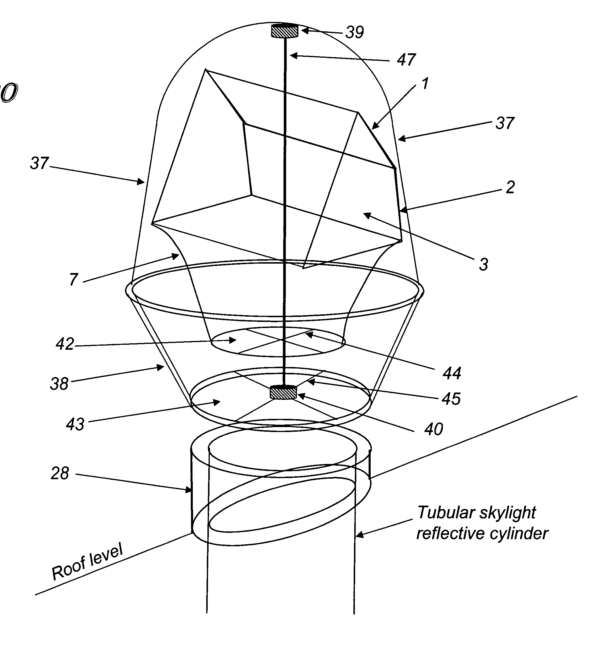
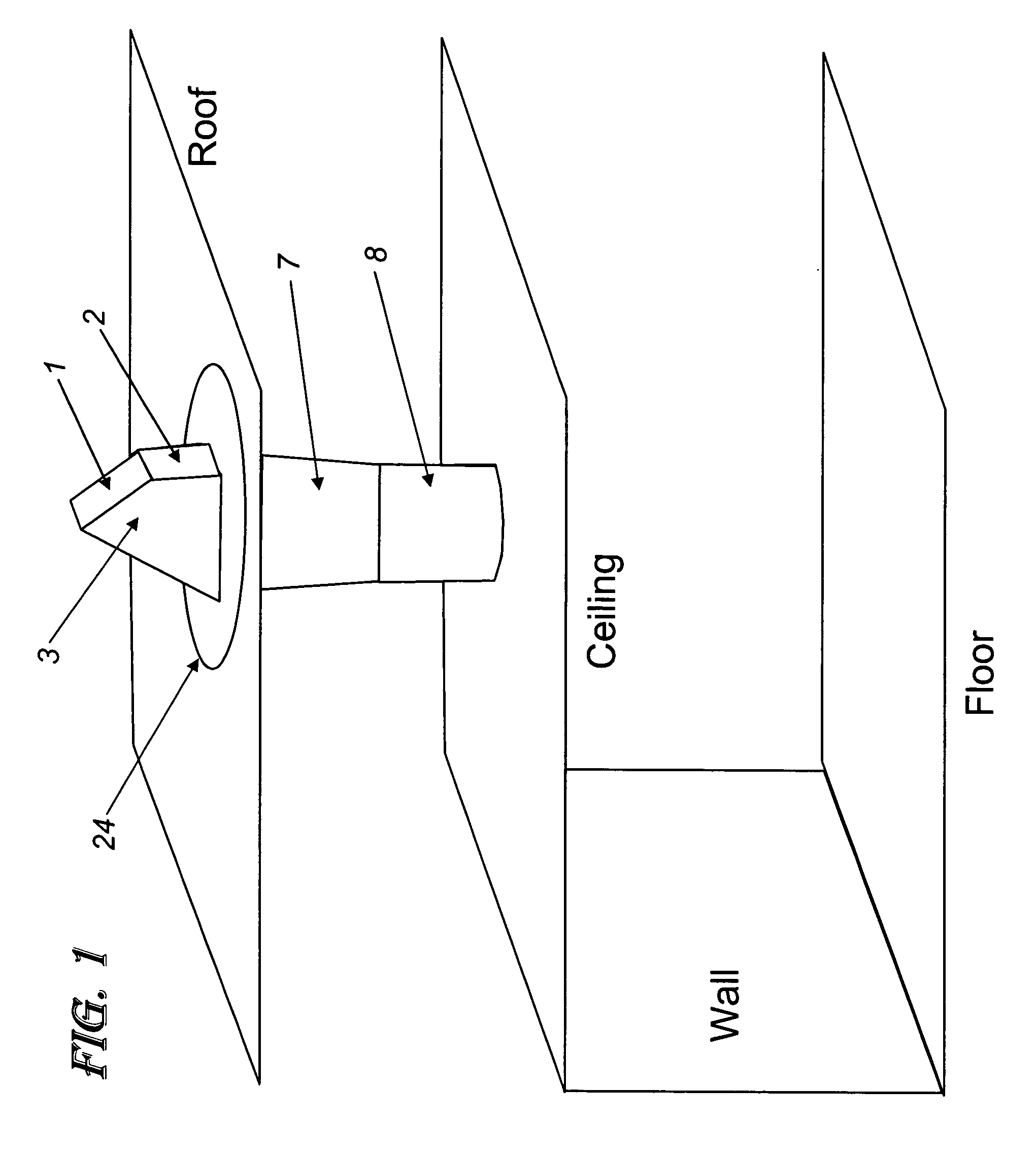
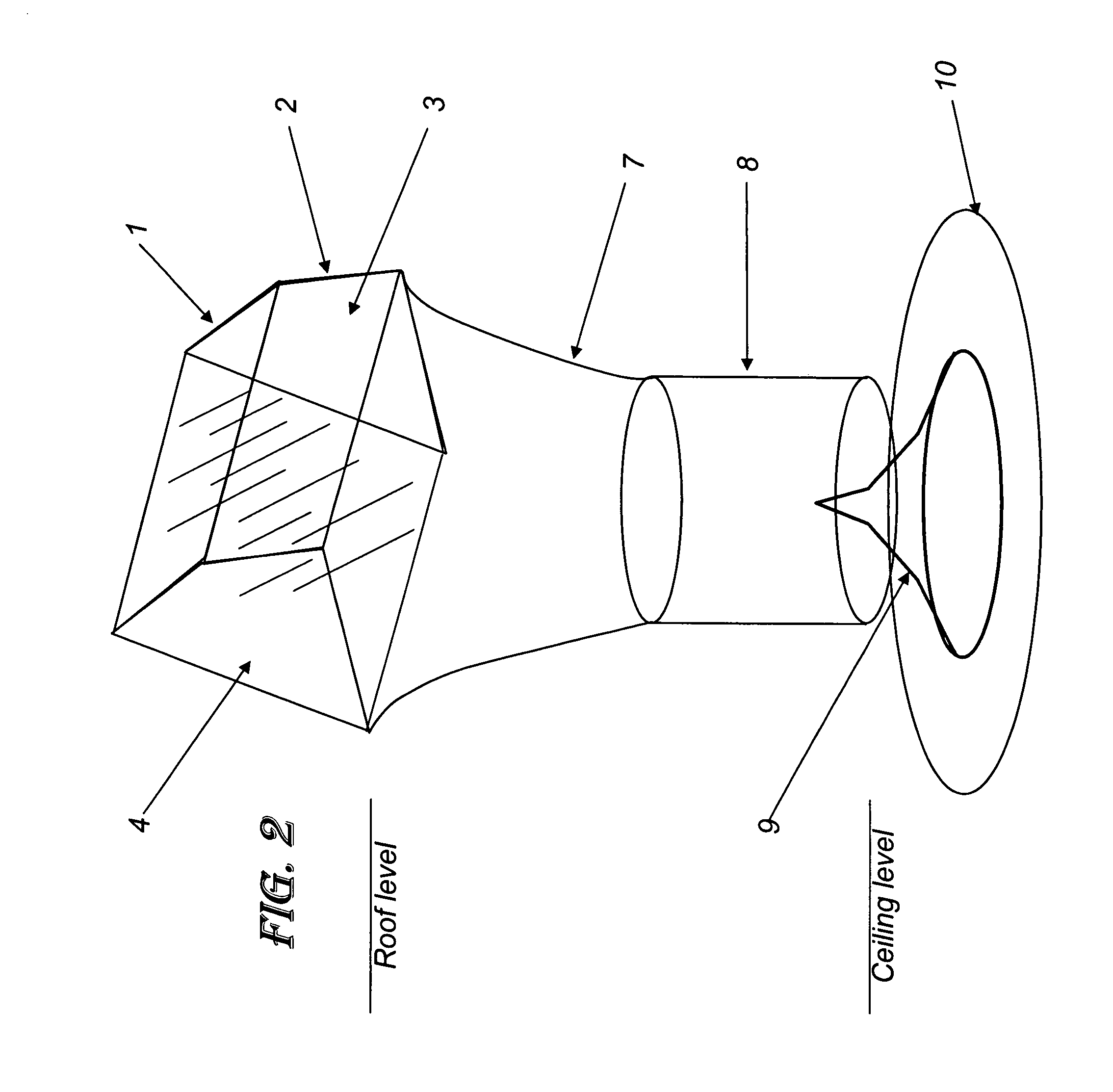
[0087]FIG. 19 provides a side view schematic illustration of this fifth embodiment of the invention. The base of the sleeve 28 fitting over a tubular skylight reflective cylinder is sealed to the roof through the use of roof flashing 30, using any of a variety of flashing techniques commonly known to roofing technicians. If needed and used, sleeve 28 is made of material strong enough to support the solar collection head and its rotating mechanism as well as to hold it tightly to the building in the event of high winds. This modification enhances the performance of the tubular skylight by increasing illumination levels at all sun angles, but preferentially more at low sun angles, making the light level in the space below more uniform throughout the day. With its larger solar collection aperture 4, tracking ability, and other design features, the added tracking head delivers more light to the light pipe 8 and improves the tubular skylight performance all day long.

[0088]Alternatively, ...

sixth embodiment

[0089]FIG. 21 provides a side view schematic illustration of this sixth embodiment of the invention. The base of the sleeve 28 fitting over a tubular skylight reflective cylinder is sealed to the roof through the use of roof flashing 30, using any of a variety of flashing techniques known to roofing technicians. If needed and used, sleeve 28 is made of material strong enough to support the solar collection head as well as to hold it tightly to the building in the event of high winds. This modification allows for very simple upgrades from a simple upwards-facing dome which is standard with tubular skylights to an active tracking system. All moving parts are protected from damage during installation or following installation from the effects of weather. By having all of the parts pre-assembled within the transparent dome, both the number of steps and the precision required for roof-top mounting are greatly reduced.

[0090]Instead of using diffusers at the bottom of the light pipe, retro...


PUM


Abstract

A direct beam solar lighting system for collecting and distributing sunlight into a room. The system includes a rotatable solar collector head to receive sunlight and to reflect the sunlight downward into a transition tube having a reflective interior surface. The light-concentrating transition tube reflects sunlight into a reflective light tube which directs the reflected sunlight through a plenum space into the room. The system includes a drive mechanism for rotating the rotatable solar collector, and a light fixture at end of the light tube to disburse said reflected sunlight onto a ceiling and a wall in the room. In an embodiment the system includes one or more homogenizing reflectors within the solar collector for collecting the sunlight and directing the sunlight more uniformly over the aperture of the transition tube. In an alternative embodiment, the solar collector includes a rotatable tiltable mirror for providing two-axis tracking.

Description

[0001]This application is a continuation-in-part of, and claims the benefit of priority to, U.S. Provisional Application No. 60 / 706,955 filed on Aug. 10, 2005.FIELD OF THE INVENTION[0002]This invention relates to solar interior lighting and, in particular, to methods, systems, apparatus and devices for implementing a direct beam solar lighting system for collecting, transmitting, and distributing sunlight into an indoor room with optional supplemental lighting.BACKGROUND AND PRIOR ART[0003]Competing technology can be divided into two categories. The first category includes conventional toplighting with rectangular roof skylights, clerestories, roof monitors, roof windows, and tubular skylights, the latter known generically as tubular daylighting devices (TDDs). Some problems exhibited by most of these include:1. Glare potential, from direct beam sunlight entering the space in such a way that people can see this very bright light directly (and indirectly by reflection from surfaces i...

Claims


Application Information

Patent Timeline
Patent Type & Authority Patents(United States)
IPC IPC(8): G02B17/00
CPCF21S11/00G01S3/7861G01S3/78
Inventor KINNEY, LAWRENCE FWALSH, JIMMCCLUNEY, WILLIAM ROSSCLER, GERALD LHUTSON, JOHN
Owner SUNFLOWER CORPORATION
Why Eureka
Try Eureka