Method for minimizing sample damage during the ablation of material using a focused ultrashort pulsed laser beam

a laser beam and focused technology, applied in the field of minimizing sample damage during the ablation of materials, can solve the problems of undesired damage beneath the surface, adversely affecting the peripheral area adjacent to the spot, and current lasers using nanosecond pulses cannot produce features with a high degree of precision and control

Inactive Publication Date: 2010-01-19
GLOBALFOUNDRIES U S INC
View PDF20 Cites 56 Cited by
  • Summary
  • Abstract
  • Description
  • Claims
  • Application Information

AI Technical Summary

Benefits of technology

[0010]In one aspect, the method of the invention provides a laser beam which defines a spot that has a lateral gaussian profile characterized in that fluence at or near the center of the beam spot is greater than the threshold fluence whereby the laser induced breakdown is ablation of an area within the spot. The maximum intensity is at the very center of the beam waist. The beam waist is the point in the beam where wave-front becomes a perfect plane; that is, its radius of curvature is infinite. This center is at radius R=0 in the x-y axis and along the Z axis, Z=0. This makes it possible to damage material in a very small volume Z=0, R=0. Thus it is possible to make features smaller than spot size in the x-y focal plane and smaller than the Rayleigh range (depth of focus) in the Z axis. It is preferred that the pulse width duration be in the femtosecond range although pulse duration of higher value may be used so long as the value is less than the pulse width defined by an abrupt or discernable change in slope of fluence breakdown threshold versus laser beam pulse width.

Problems solved by technology

Although the laser beam is focused onto an area having a selected diameter, the effect of the beam extends beyond the focused area or spot to adversely affect peripheral areas adjacent to the spot.
Sometimes the peripheral area affected is several times greater than the spot itself This presents a problem, particularly where tissue is affected in a medical procedure.
In the field of laser machining, current lasers using nanosecond pulses cannot produce features with a high degree of precision and control, particularly when nonabsorptive wavelengths are used.
Applicants have discovered that it is undesirable to focus at or beneath the surface since this results in undesired damage beneath the surface, in particular to the substrate (or underlayer) on which the material that is to be removed is disposed.
This is particularly a problem where the underlayer is very sensitive to the laser light and / or can be easily damaged by the laser light.

Method used


Image

  • Method for minimizing sample damage during the ablation of material using a focused ultrashort pulsed laser beam
  • Method for minimizing sample damage during the ablation of material using a focused ultrashort pulsed laser beam
  • Method for minimizing sample damage during the ablation of material using a focused ultrashort pulsed laser beam

Examples


example 1

Opaque Material

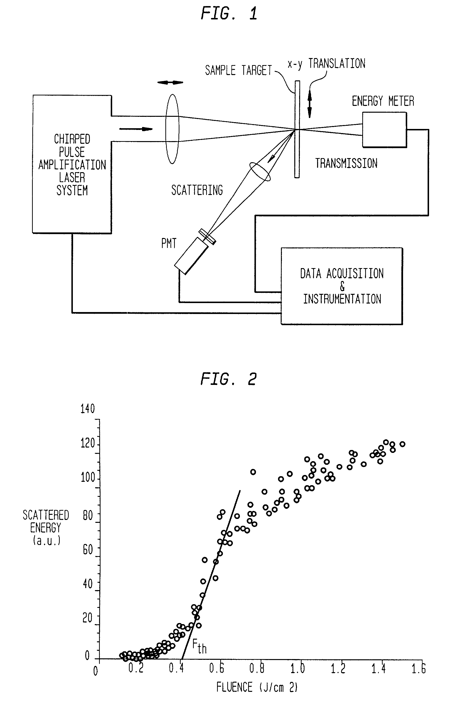
[0042]FIG. 1 shows an experimental setup for determining threshold fluence by determining scattered energy versus incident fluence and by determining threshold fluence versus pulse width. The system includes means for generating a pulsed laser beam as described earlier, and means, typically a lens, for collecting emission from the target to a photomultiplier tube. Change of transmission through a transparent sample is measured with an energy meter.

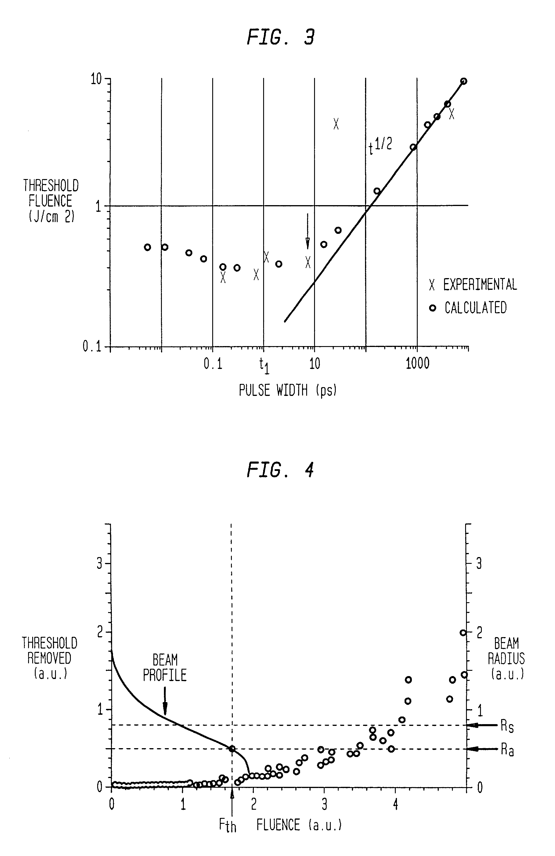
[0043]FIG. 2 shows a plot of data obtained from an absorbing medium which is gold using 150 fs pulse and FIG. 3 shows threshold fluence pulse width. The arrow in FIG. 3 identifies the point at which the relationship between the threshold fluence and pulse width varies dramatically.

[0044]In experimental conditions with wavelength of 800 nm and 200 fs pulses on gold (FIG. 3), the absorption depth is 275 A with a diffusion of 50 A. In the case of nanosecond pulses the diffusion length, which is on the order of 10 μm (micron) in...

example 2

Transparent Material

[0054]A series of tests were performed on an SiO2 (glass) sample to determine the laser induced breakdown (LIB) threshold as a function of pulse width between 150 fs-7 ns, using a CPA laser system. The short pulse laser used was a 10 Hz Ti:Sapphire oscillator amplifier system based on the CPA technique. The laser pulse was focused by an f=25 cm lens inside the SiO2 sample. The Rayleigh length of the beam is ˜2 mm. The focused spot size was measured in-situ by a microscope objective lens. The measured spot size FWHM (full at half max) was 26 μm in diameter in a gaussian mode. The fused silica samples were made from Corning 7940, with a thickness of 0.15 mm. They were optically polished on both sides with a scratch / dig of 20−10. Each sample was cleaned by methanol before the. Thin samples were used in order to avoid the complications of self-focusing of the laser pulses in the bulk. The SiO2 sample mounted on a computer controlled motorized X-Y translation stage. E...

example 3

Tissue

[0057]A series of experiments was performed to determine the breakdown threshold of cornea as a function of laser pulse width between 150 ns, using a CPA laser system. As noted earlier, in this CPA laser system, laser pulse width can be varied while all other experimental parameters (spot size, wavelength, energy, etc.) remain unchanged. The laser was focused to a spot size (FWHM) of 26 μm in diameter. The plasma emission was recorded as a function of pulse energy in order to determine the tissue damage threshold. Histologic damage was also assessed.

[0058]Breakdown thresholds calculated from plasma emission data revealed deviations from the scaling law, Fth. alpha. T1 / 2, as in the case of and glass. As shown in FIG. 9, the scaling law of the fluence threshold is true to about 10 ps, and fail when the pulse shortens to less than a few picoseconds. As shown in FIGS. 10 and 11, the ablation or LIB threshold varies dramatically at high (long) pulse width. It is very precise at sho...


PUM

PropertyMeasurementUnit
energyaaaaaaaaaa
spot sizeaaaaaaaaaa
sizeaaaaaaaaaa

Abstract

In one aspect the invention provides a method for laser induced breakdown of a material with a pulsed laser beam where the material is characterized by a relationship of fluence breakdown threshold (Fth) versus laser beam pulse width (T) that exhibits an abrupt, rapid, and distinct change or at least a clearly detectable and distinct change in slope at a predetermined laser pulse width value. The method comprises generating a beam of laser pulses in which each pulse has a pulse width equal to or less than the predetermined laser pulse width value. The beam is focused above the surface of a material where laser induced breakdown is desired. The region of least confusion (minimum beam waist or average spot size) is above the surface of the material in which laser induced breakdown is desired since the intensity of the beam falls off in the forward direction, preferably the region of the beam at or within the surface is between the region of least confusion and sufficient to remove material and the minimum intensity necessary for laser induced breakdown of the material to be removed, most preferably the region of minimum intensity is disposed at the surface of the material to be removed. The beam may be used in combination with a mask in the beam path. The beam or mask may be moved in the x, y, and Z directions to produce desired features. The technique can produce features smaller than the spot size and Rayleigh range due to enhanced damage threshold accuracy in the short pulse regime.

Description

[0001]This is a continuation-in-part of application Ser. No. 09 / 210,226, filed on Dec. 11, 1998 now U.S. Pat. No. 6,333,485.FIELD OF THE INVENTION[0002]This invention relates generally to methods utilizing lasers for modifying internal and external surfaces of material such as by ablation or changing properties in structure of materials. This invention may be used for a variety of materials.BACKGROUND OF THE INVENTION[0003]Laser induced breakdown of a material causes chemical and physical changes, chemical and physical breakdown, disintegration, ablation, and vaporization. Lasers provide good control for procedures which require precision such as inscribing a micro pattern. Pulsed rather than continuous beams are more effective for many procedures, including medical procedures. A pulsed laser beam comprises bursts or pulses of light which are of very short duration, for example, on the order of 10 nanoseconds in duration or less. Typically, these pulses are separated by periods of q...

Claims


Application Information

Patent Timeline
Patent Type & Authority Patents(United States)
IPC IPC(8): B23K26/36B23K26/06A61B18/26G03F1/00
CPCA61B18/26B23K26/0635B23K26/0656B23K26/365B23K26/4005B23K26/403B23K26/407G03F1/0092G03F1/72A61B18/20A61F9/00814B23K26/0624B23K26/066B23K26/40A61B18/203A61B2018/00577A61B2018/00625A61F9/0084B23K26/361B23K2103/30B23K2103/50A61F2009/00863B23K26/362B23K26/402
Inventor HAIGHT, RICHARD ALANLONGO, PETER P.MORRIS, DANIEL PETERWAGNER, ALFRED
Owner GLOBALFOUNDRIES U S INC
Why Eureka
Try Eureka