
Slave latch controlled retention flop with lower leakage and higher performance

a retention flop and latch control technology, applied in the field of integrated circuits, can solve the problems of inoperable circuits or less robust circuits at lower voltages, and achieve the effects of reducing silicon area, reducing leakage current, and desirable performan

Active Publication Date: 2010-01-26
TEXAS INSTR INC
View PDF3 Cites 31 Cited by
  • Summary
  • Abstract
  • Description
  • Claims
  • Application Information

AI Technical Summary

Benefits of technology

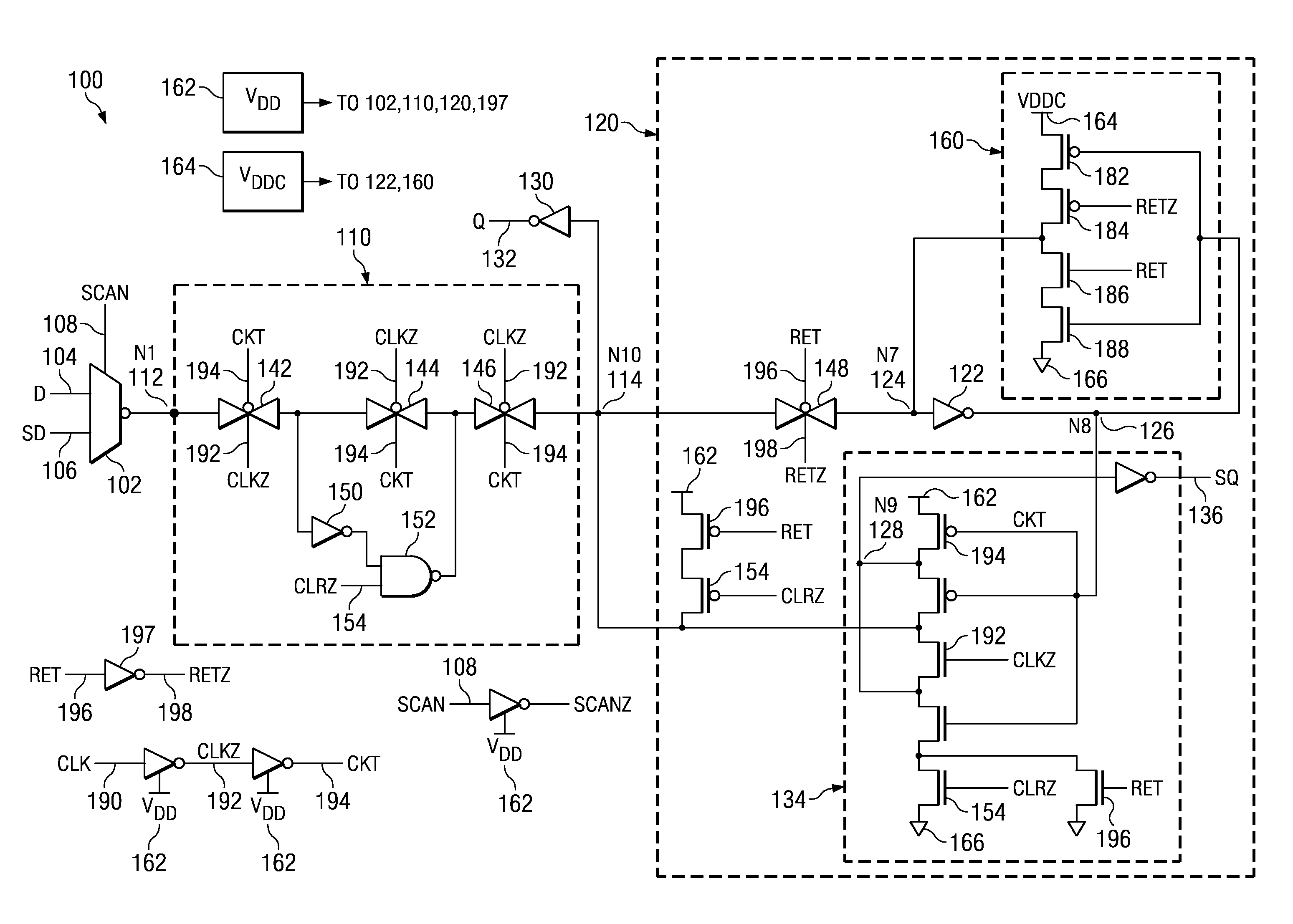
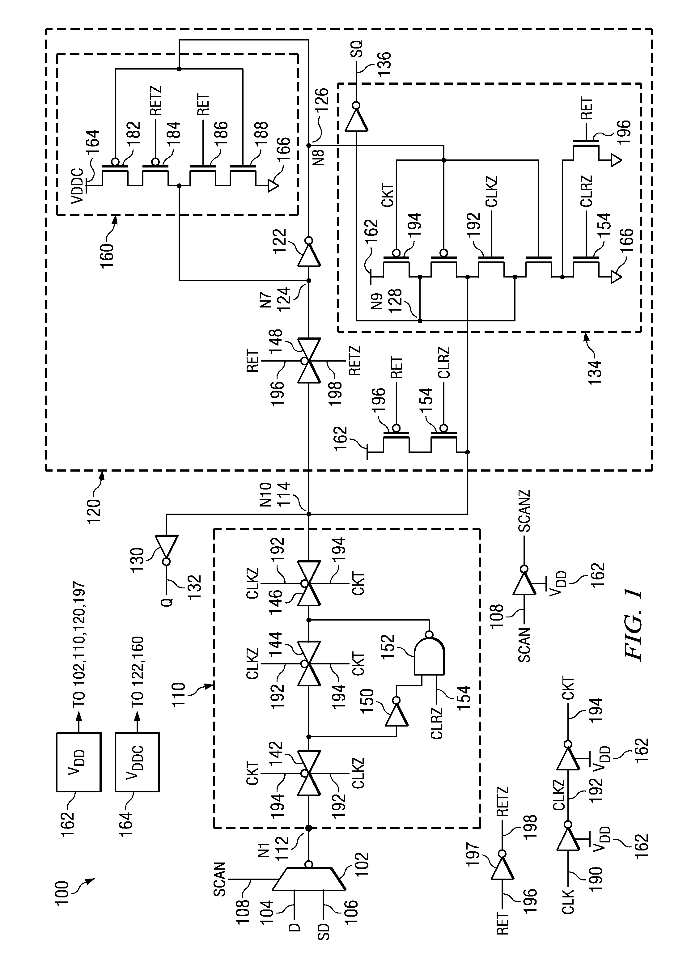
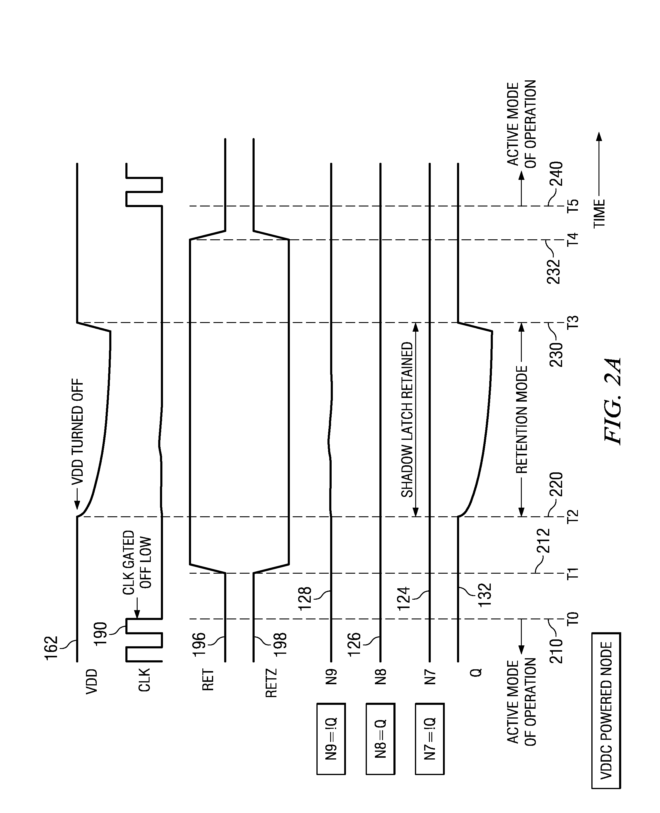
[0007]Several advantages are achieved by the method and system according to the illustrative embodiments presented herein. The embodiments advantageously provide an improved apparatus and method for data retention in a standby power mode. The improved apparatus and method for data retention advantageously provides a lower leakage current while providing desirable performance and desirable reduction in silicon area, especially when compared to the leakage current, silicon area, and performance characteristics of two data retention flip flop circuits used as a benchmark. The particular values for the desirable attributes used as a benchmark may be application specific, e.g., performance to be within 90% of a benchmark, reduction in leakage current to be at least 15% of a benchmark, reduction in silicon area to be within plus or minus 5% of a benchmark, and similar others. The lower leakage current is achieved by reducing the number of active devices used for data retention compared to the benchmark circuits, the active devices being powered by a standby power source in the standby power mode to produce the leakage current. The data retention feature is advantageously embedded in a slave latch portion of a data retention flip flop, thereby minimizing the impact on the normal operation of the flip flop. The improved apparatus and method for data retention may be configured to advantageously exclude gating of the clock path, e.g., the clock is only buffered with two inverters to derive CLKZ and CKT signals without having any additional gating circuitry for deriving other clock signals, thereby improving the performance and robustness.

Problems solved by technology

However, presence of leakage current during the standby power mode represents a challenge for designing portable devices having an extended battery life.
However, improvement in one parameter is often achieved at the cost of others, e.g., improvement in performance may be achieved at the cost of an undesirable increase in leakage current or silicon area or both, or an improvement in leakage current may make circuit inoperable or become less robust at lower voltages of a power source.

Method used


Image

  • Slave latch controlled retention flop with lower leakage and higher performance
  • Slave latch controlled retention flop with lower leakage and higher performance
  • Slave latch controlled retention flop with lower leakage and higher performance

Examples


Embodiment Construction

[0017]Novel features believed characteristic of the present disclosure are set forth in the appended claims. The disclosure itself, however, as well as a preferred mode of use, various objectives and advantages thereof, will best be understood by reference to the following detailed description of an illustrative embodiment when read in conjunction with the accompanying drawings. The functionality of various circuits, devices or components described herein may be implemented as hardware (including discrete components, integrated circuits and systems-on-a-chip ‘SoC’), firmware (including application specific integrated circuits and programmable chips) and / or software or a combination thereof, depending on the application requirements.

[0018]Similarly, the functionality of various mechanical elements, members, or components for forming modules, sub-assemblies and assemblies assembled in accordance with a structure for an apparatus may be implemented using various materials and coupling ...


PUM


Abstract

In a method and apparatus for data retention, a first latch latches a data input and a second latch that is coupled to the first latch retains the data input while the first latch is inoperative in a standby power mode. The second latch includes a second latch inverter having an inverter input and an inverter output. A switching circuit, which may be implemented as a tristate inverter, is coupled to the inverter output, the inverter input, and a retention signal. The switching circuit is operable in the standby power mode to assert a logic state at the inverter input responsive to the retention signal. The logic state is in accordance with the data input retained in the standby power mode. A standby power source is operable to provide power in the standby power mode to the second latch inverter, the switching circuit and the retention input.

Description

BACKGROUND[0001]The present invention is related in general to integrated circuits (ICs), and more particularly to an apparatus and method for providing data retention with reduced power consumption.[0002]Many portable electronic devices such as cellular phones, digital cameras / camcorders, personal entertainment devices, laptop or palmtop computers, and video games operate on batteries. During periods of inactivity the device may not perform processing operations and may be placed in a power-down or standby power mode to conserve power. Power provided to ICs within the electronic device may be turned off in a standby power mode. Data retention circuits such as flip flops or latches within the device may be used to store status information for later use prior to the device entering the standby power mode. The data retention latch, which may also be referred to as a shadow latch or a balloon latch, is typically powered by a separate ‘always on’ power supply. However, presence of leaka...

Claims


Application Information

Patent Timeline
Patent Type & Authority Patents(United States)
IPC IPC(8): H03K3/356
CPCH03K3/012H03K3/356147H03K3/35625
Inventor RAO, BINDU PRABHAKARGURURAJARAO, SUMANTH KATTESHAH, DHARIN N.
Owner TEXAS INSTR INC
Learn More