Electric field generator incorporating a slow-wave structure

a technology of electric field generator and slow-wave structure, which is applied in the direction of resistance/reactance/impedence, waveguides, instruments, etc., can solve the problems of increasing background noise level, adversely affecting the performance of electronic systems, and electromagnetic energy may produce varying levels of interference, so as to increase the external inductance of the transmission line structure, increase the length of the current path, and increase the effect of path length

Inactive Publication Date: 2010-02-02
TDK CORPARATION
View PDF4 Cites 228 Cited by
  • Summary
  • Abstract
  • Description
  • Claims
  • Application Information

AI Technical Summary

Benefits of technology

[0019]In one example, the inductively loaded transmission line structure may include one or more helically shaped conductors, such that the transmission line structure is oriented along a longitudinal axis of the helix. In some cases, the helix may be arranged along and around an insulating support structure. In other cases, the transmission line structure may include a magnetic core arranged within the helix and along the longitudinal axis of the helix. The helix, however, may alternatively be fabricated such that neither an insulating support structure nor a magnetic core is included in the transmission line structure. In such a case, the helically shaped conductors may increase the length of the current path to increase the external inductance of the transmission line structure. An increase in path length typically reduces the phase velocity of the wave propagating along the conductive elements of the transmission line structure, thereby increasing the electric field generated by the transmission line structure.
[0020]In another example, the inductively loaded transmission line structure may include a conductor having a conductive surface arranged in proximity to a magnetic material structure (e.g., a structure fabricated with a magnetic material such as ferrite). In some cases, a magnetic mater...

Problems solved by technology

Electromagnetic energy is considered electromagnetic interference (EMI) when it adversely affects the performance of an electronic system.
All electronic devices create some form of electromagnetic energy that potentially interferes with the operation of other electrical devices outside the system (inter-system) or within the system (intra-system).
Electromagnetic energy may also produce varying levels of interference.
On a low interference level, EMI may produce “cross-talk” between conductive paths, which tends to increase the background noise level within signals traversing the paths.
On the other hand, however, EMI can cause significant problems and even system failure in devices that are highly sensitive to electromagnetic radiation, such as automotive electronic systems (e.g. anti-lock braking systems).
This broadband generation of high-intensity electromagnetic fields typically presents a formidable challenge to designers.
However, an antenna may be subject to severe physical limitations, such as limited bandwidth, field pattern frequency dependency, and wide spatial variations in field intensity for a given frequency.
Although the open-circuit E-field generator may...

Method used


Image

  • Electric field generator incorporating a slow-wave structure
  • Electric field generator incorporating a slow-wave structure
  • Electric field generator incorporating a slow-wave structure

Examples


Embodiment Construction

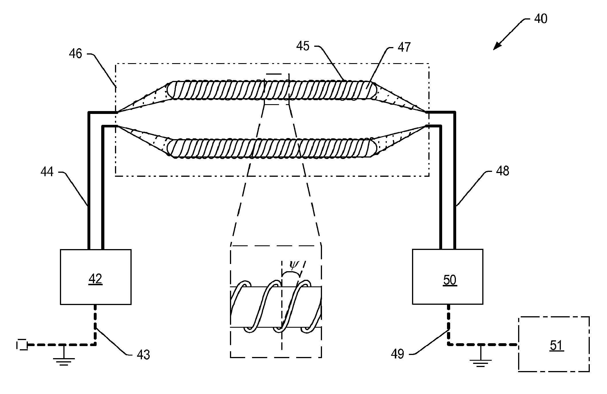
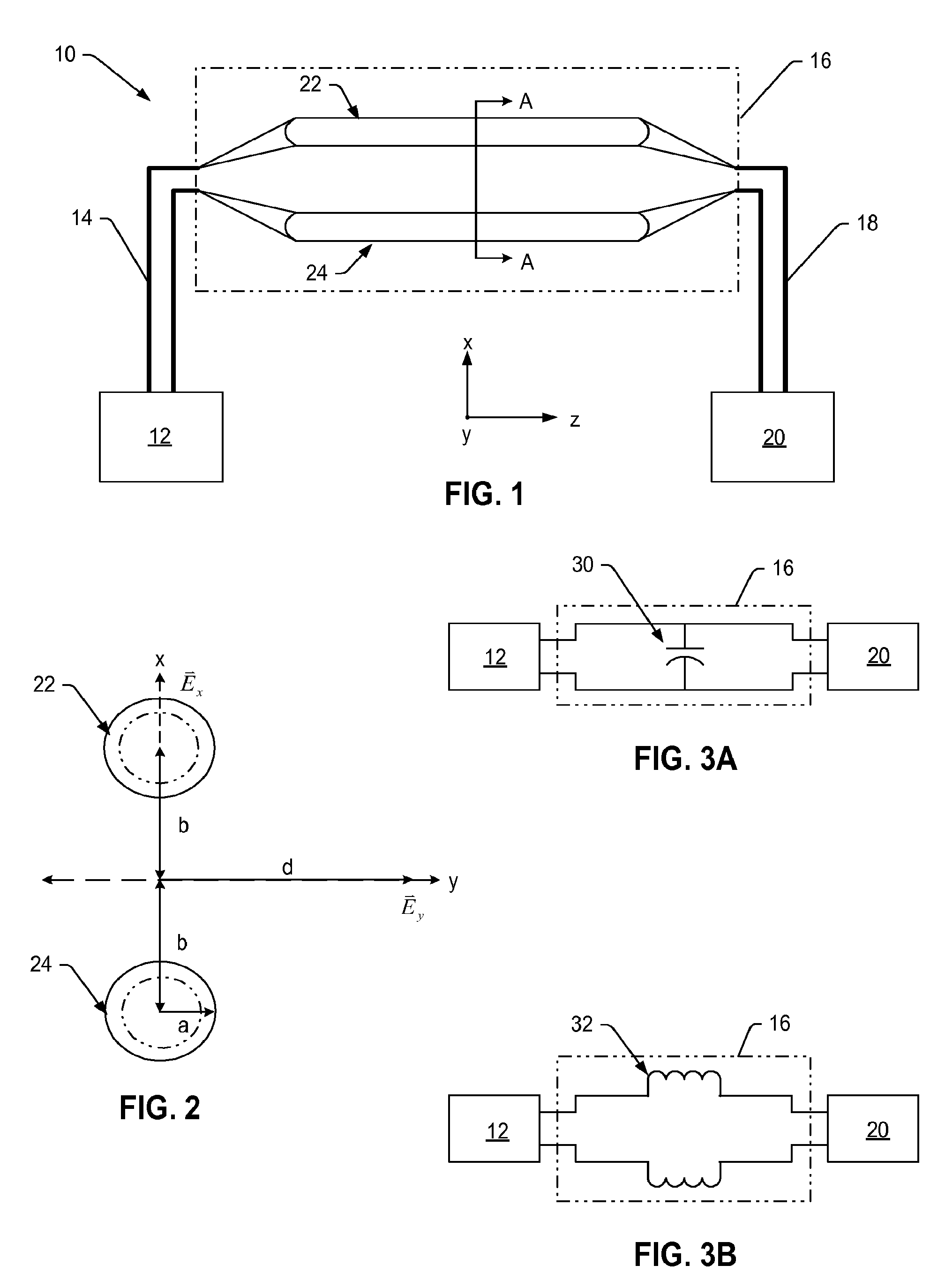
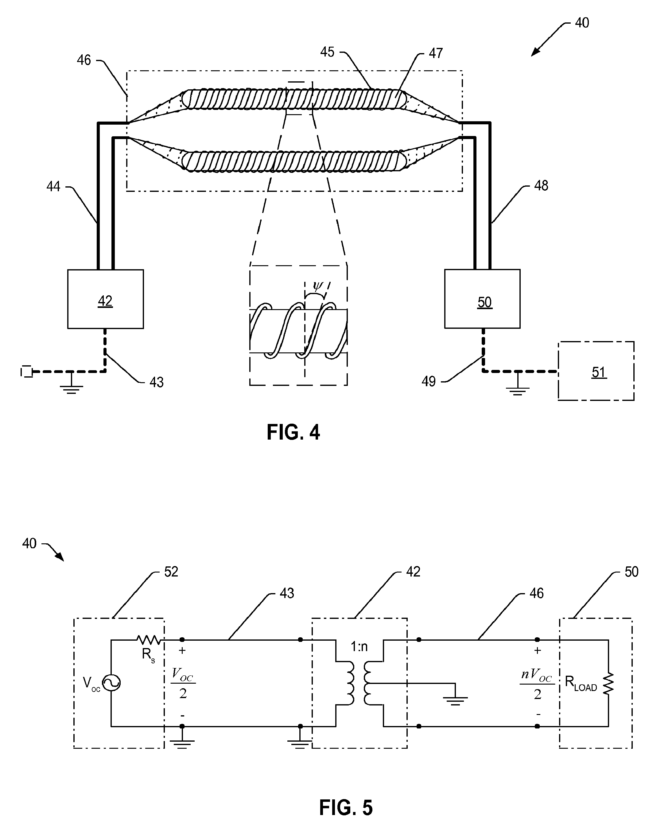
[0038]Turning now to the drawings, FIG. 1 is a block diagram illustrating one embodiment of a transmission line E-field generator 10 including a pair of conductive elements (or “conductors”) 22, 24 driven by a power source 12 and terminated by a balanced resistive load 20. In this manner, the transmission line generator of the present embodiment is essentially a two-conductor, balanced transmission line, which supports wave propagation in a transverse electromagnetic (TEM) mode. In TEM mode, the generated electric and magnetic fields are both transverse (i.e., x and y directions) to the direction of wave propagation along the longitudinal axis (z) of the transmission line. As such, the electric and magnetic fields along the longitudinal axis are essentially zero (i.e., Ez=Hz=0), while the transverse electric and magnetic fields can be expressed as quasi-static vector quantities. In other words, the field distribution over a transverse plane of a transmission line is substantially a ...


PUM


Abstract

An improved E-field generator including a slow-wave transmission line structure is provided herein. In some cases, the improved E-field generator may include an inductively-loaded slow-wave transmission line structure driven by a power source at one end of the structure and terminated by a load at the other end of the structure. In other cases, the improved E-field generator may include a capacitively-loaded slow-wave transmission line structure. In either case, the improved E-field generator provides a frequency-independent, significantly increased electric field at a distance spaced from the generator without altering the dimensions of the generator and/or the input power supplied to the generator. The increase in generated field intensity is achieved by decreasing the phase velocity of the electromagnetic wave propagating along the parallel elements of the generator.

Description

BACKGROUND OF THE INVENTION[0001]1. Field of the Invention[0002]This invention relates to electromagnetic compatibility (EMC) testing and, more particularly, to electric field generating devices, or energy transducers used for exposing devices under test to high-intensity electromagnetic fields over a large range of frequencies.[0003]2. Description of the Related Art[0004]The following descriptions and examples are not admitted to be prior art by virtue of their inclusion within this section.[0005]Electromagnetic energy is considered electromagnetic interference (EMI) when it adversely affects the performance of an electronic system. All electronic devices create some form of electromagnetic energy that potentially interferes with the operation of other electrical devices outside the system (inter-system) or within the system (intra-system). As such, all electronic devices are capable of interfering with other devices (emission), or being affected by the emissions from other devices...

Claims


Application Information

Patent Timeline
IPC IPC(8): H01P9/02
CPCH01P9/02
Inventor MCLEAN, JAMES S.
Owner TDK CORPARATION
Why Eureka
Try Eureka