Apparatus for distributed ignition of fuels by light sources

a technology of distributed ignition and light source, which is applied in the direction of burner ignition devices, lighting and heating apparatus, physical/chemical process catalysts, etc., can solve the problems of high cost, heavy weight, and high initial burn rate of fuel, and achieve the effects of high initial burn rate, and high initial burn ra

Inactive Publication Date: 2010-02-23
ERC
View PDF5 Cites 9 Cited by
  • Summary
  • Abstract
  • Description
  • Claims
  • Application Information

AI Technical Summary

Problems solved by technology

For example, improper ignition during the firing of a rocket engine during lift-off can lead to a catastrophic engine failure and possible loss of the spacecraft and human life.
Also, the ignition characteristics in a gasoline-fueled automotive engine can strongly affect the fuel's initial burn rate, the chamber's combustion efficiency and the exhaust stream's emission profile.
Other ignition methods such as plasma jet injection or flame jet initiation, and high-power laser ignition are all bulky, heavy and expensive to operate.
Another disadvantage of these ignition systems, with the exception of perhaps lasers, is that once they are installed on an engine, the ignition location remains fixed with respect to the combustion chamber.
However, using the above described fixed point ignition techniques, multi-point ignition within a chamber can only be achieved by repeated implementation of the ignition hardware, which spatially can be very restrictive to attain as well as increasing engine size and mass over a single-point ignition system.
Current ignition methods also suffer from one or more other disadvantages such as combustion instability, start-up transients which decrease engine efficiency, and increased pollutant emissions.

Method used


Image

  • Apparatus for distributed ignition of fuels by light sources
  • Apparatus for distributed ignition of fuels by light sources
  • Apparatus for distributed ignition of fuels by light sources

Examples


example 1

RP-1 (Refined Petroleum) and SWCNTs Carrying Nano-Metallic Particles

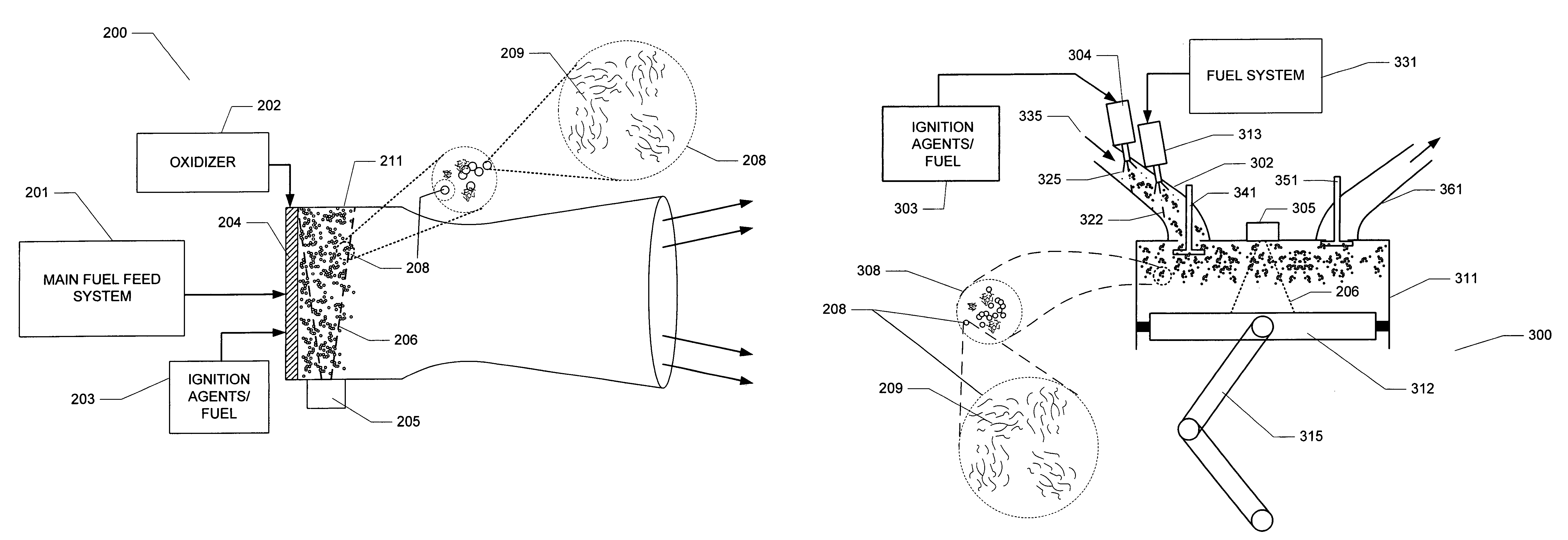
[0060]2 milligrams of SWCNTs carrying nano-metallic particles were placed onto a microscope glass slide placed on a lab jack situated 20 mm directly under a camera flash-light unit. The air above the sample of SWCNTs was enriched with O2 using a Teflon tubing (¼″ O.D.) that had the gas flowing at 500 sccm (standard cubic centimeter per minute). The tube ending was typically 3-4 cm from the ignition mixture. 1-2 drops (0.1-0.2 ml) of RP-1 were added to the SWCNTs carrying nano-metallic particles using a Pasteur pipette. The sample was subjected to a single flash exposure and the ensuing event recorded using a color CCD video camera. When the flash unit window was at distances greater than 10 mm from the glass slide, only a characteristic “pop” was audible. The SWCNTs absorb the luminous output of the flash and cause rapid heating within, followed by the release of this energy through a photo-acoustic pulse. The glass...

example 2

Acetone with SWCNT Carrying Nano-Metallic Particles

[0061]Based upon the observations in the experiments detailed above, it appeared that the optimum exposure distance range for the experiment conditions was 5-6 mm. When 1-2 drops (0.1-0.2 ml) of acetone are added to the ignition agents and subjected to a single flash exposure, a violent flame jet was observed. No such flames were observed with only acetone present. Mixtures of acetone and activated carbon instead of SWCNTs carrying nano-metallic particles failed to ignite under otherwise identical experimental conditions. Also, when these nano-metallic ignition agents were completely immersed in excess acetone, ignition was not possible.

example 3

Nitromethane with SWCNTs Carrying Nano-Metallic Particles

[0062]2 drops (0.2 ml) of nitromethane were added to 2 milligrams of SWCNTs carrying nano-metallic particles placed on a glass slide and subjected to a single flash exposure in the O2 enriched air conditions. Accompanying the characteristic photo-acoustic pulse was the formation of a vaporized nitromethane cloud that then ignited into a bright-blue flame. On removal of O2, ignition was not possible but the nitromethane cloud was consistently seen after every flash exposure. The extent of vaporization was deduced to increase with reduction in the exposure distance and increase in the flash output.


PUM

PropertyMeasurementUnit
distanceaaaaaaaaaa
distancesaaaaaaaaaa
distanceaaaaaaaaaa

Abstract

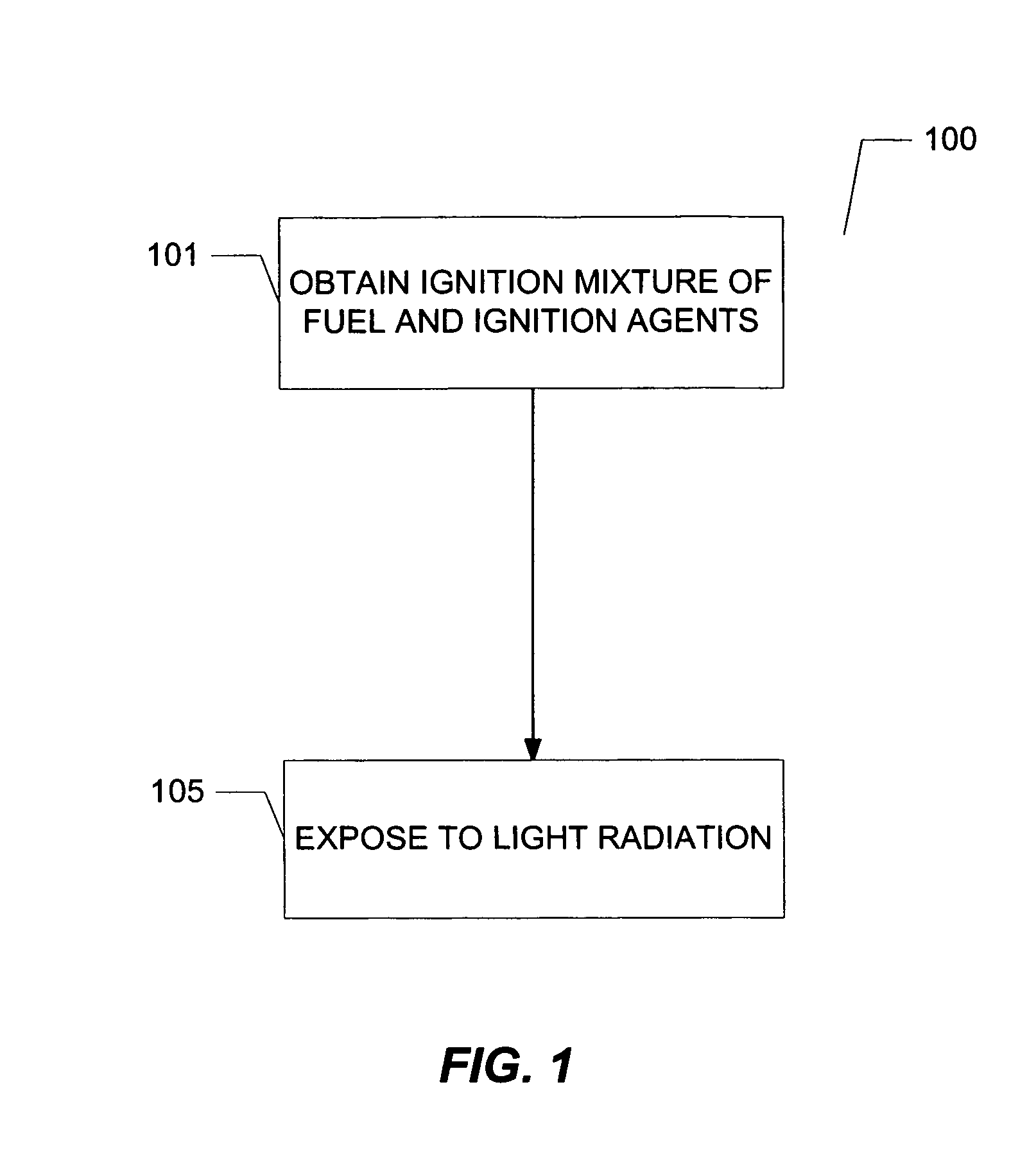
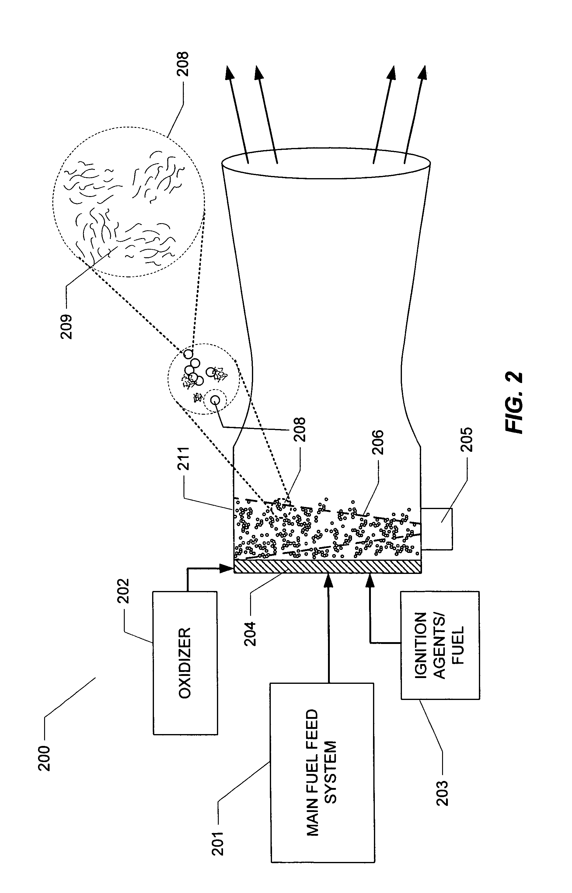
An apparatus for distributed ignition is disclosed wherein a combustion fuel and an ignition mixture are combined where the ignition mixture comprises ignition agents and fuel and where ignition agents can be nano-metallic particles in combination with single-walled carbon nano-tubes (SWCNTs). The combination of ignition mixture and combustion fuel in the presence of oxygen are exposed to light causing heating of the ignition agents and combustion of the fuel within which the ignition agents are interspersed. A system for igniting fuels using the method is also disclosed.

Description

CROSS-REFERENCE TO RELATED APPLICATIONS[0001]This application is a divisional application under 35 U.S.C. § 121 of pending U.S. patent application Ser. No. 10 / 888,240, filed Jul. 9, 2004.STATEMENT REGARDING FEDERALLY SPONSORED RESEARCH OR DEVELOPMENT[0002]The U.S. Government has a paid-up license in this invention and the right in limited circumstances to require the patent owner to license others on reasonable terms as provided for by the terms of Contract No. F04611-99-C-0025 awarded by the U.S. Air Force.BACKGROUND[0003]1. Field[0004]The present invention relates to distributed ignition (or heating) of fuels, propellants, energetic materials and related combustible materials, and in particular it relates to the use of certain ignition agents, in ignition of fuels, propellants, energetic materials, and related combustible materials.[0005]2. Description of the Related Art[0006]Many industrial processes that utilize chemical reactions in their applications often require an initiatio...

Claims


Application Information

Patent Timeline
Patent Type & Authority Patents(United States)
IPC IPC(8): C10L1/12
CPCB82Y30/00F23K5/10B01J21/185B01J23/44B01J23/74F23D2207/00F23K2401/10F23K2400/10
Inventor CHEHROUDI, BEHROUZVAGHJIANI, GHANSHYAM L.KETSDEVER, ANDREW DAVID
Owner ERC
Why Eureka
Try Eureka