
Method for measuring luminescence at a luminescence detection workstation

a luminescence detection and workstation technology, applied in the direction of fluorescence/phosphorescence, dosimeters, instruments, etc., can solve the problems of stray light from external light sources or adjacent samples, need for high-speed processing, and chemiluminescence or bioluminescence may diminish, so as to minimize crosstalk and minimize crosstalk

Inactive Publication Date: 2010-03-02
APPL BIOSYSTEMS INC
View PDF17 Cites 4 Cited by
  • Summary
  • Abstract
  • Description
  • Claims
  • Application Information

AI Technical Summary

Benefits of technology

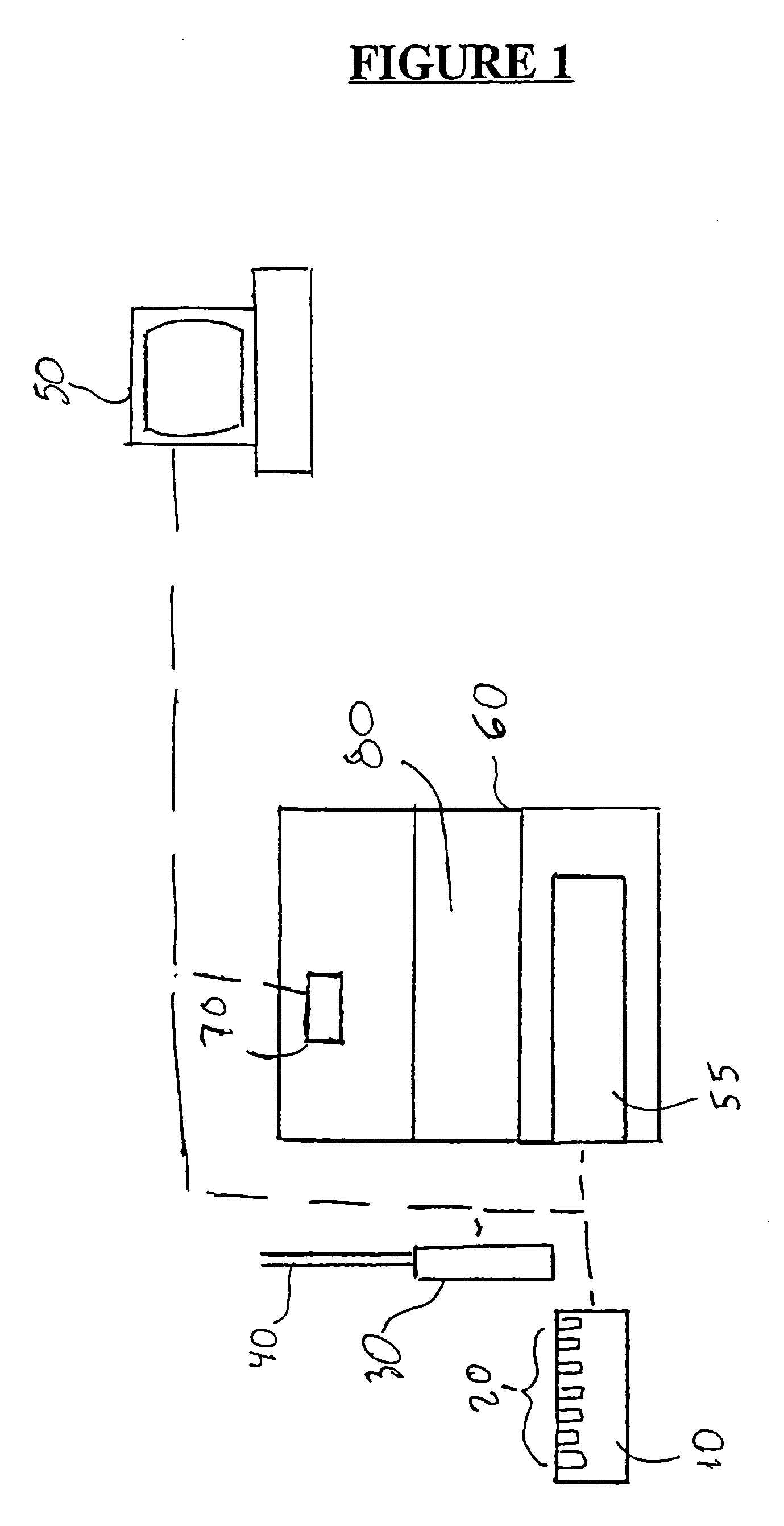
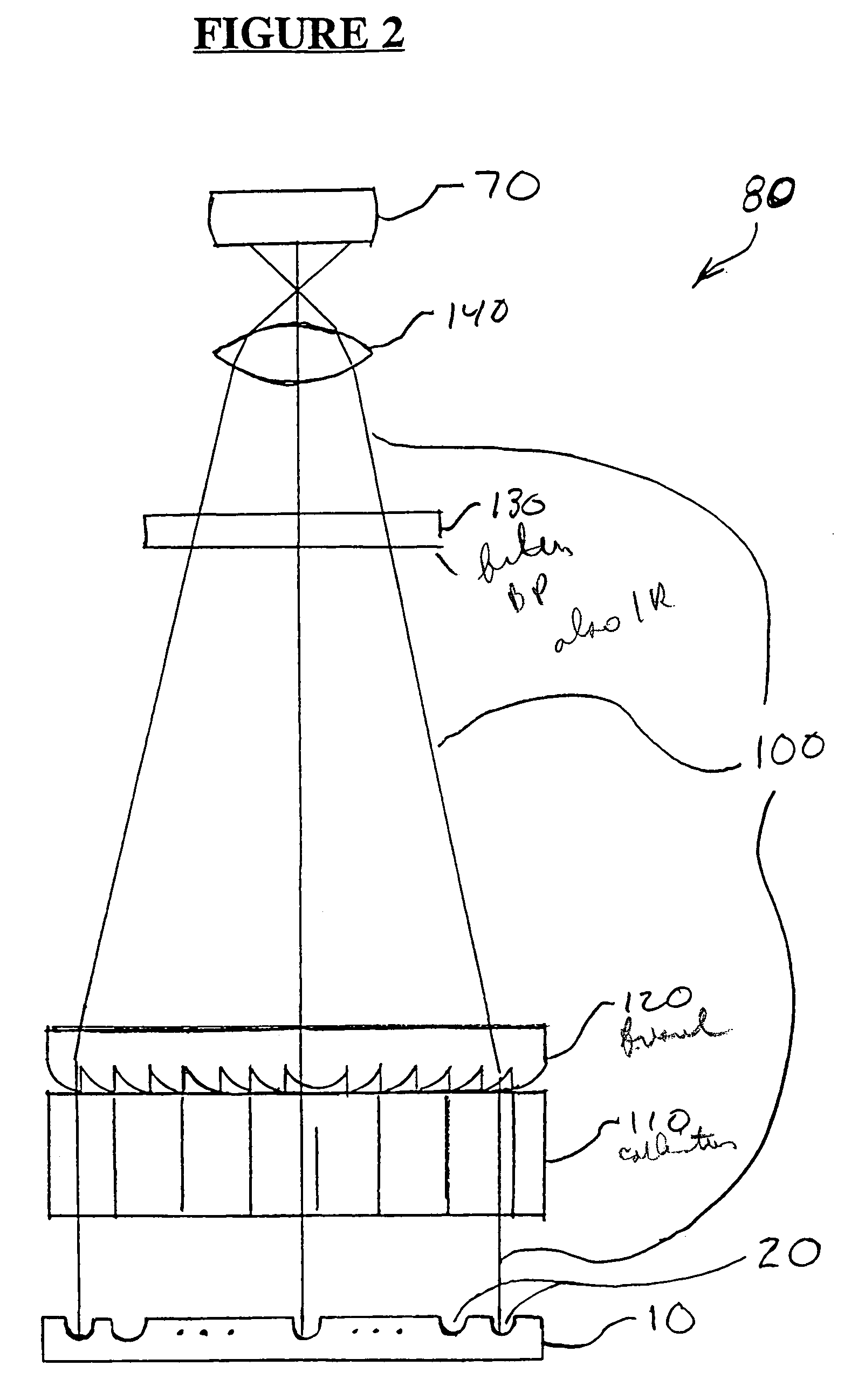
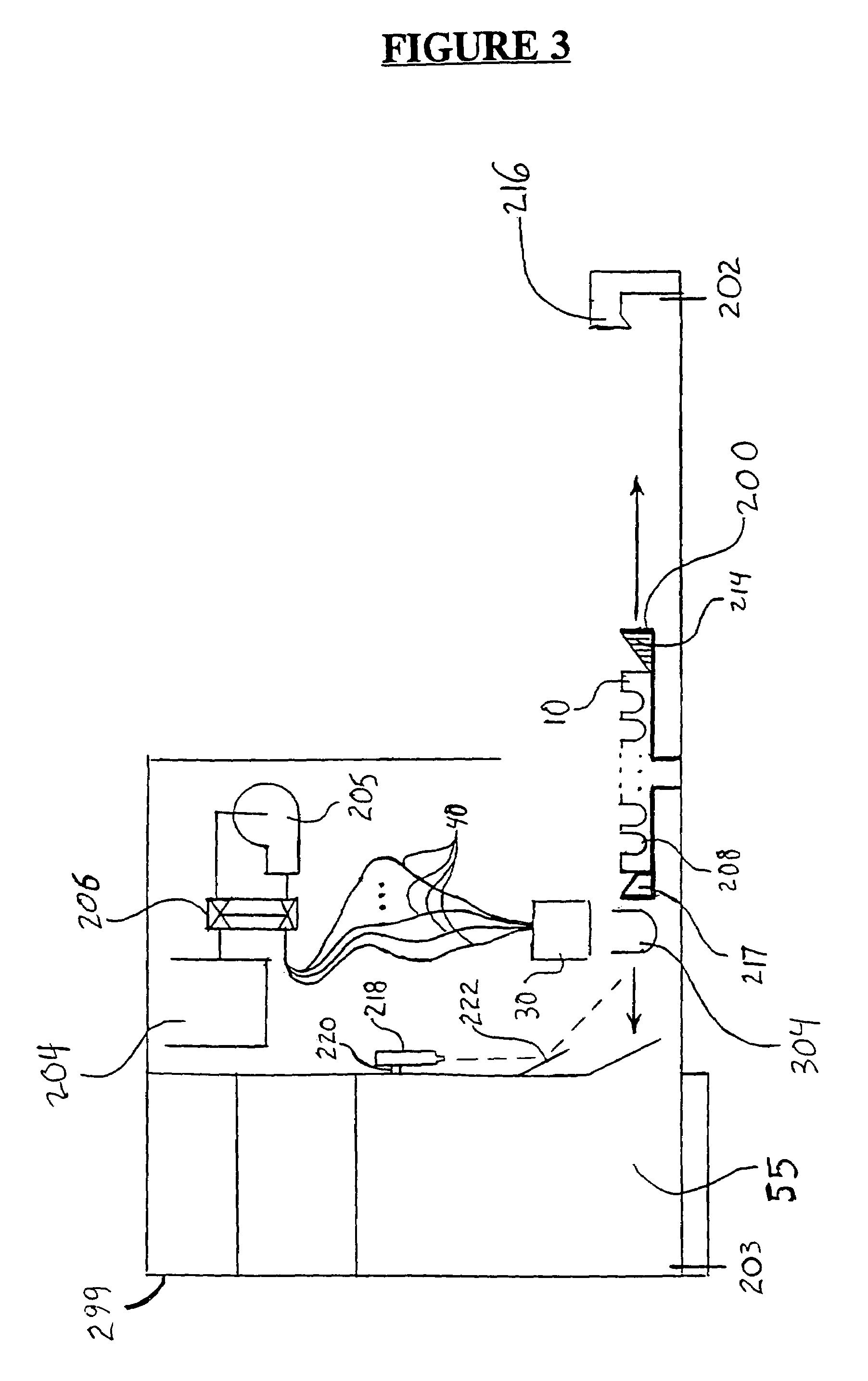
The present invention provides a luminescence detecting apparatus that can analyze luminescent samples simultaneously. It can handle multiple samples in well plates with a large number of wells, and can also analyze low light level samples while minimizing crosstalk from adjacent samples. The apparatus uses a Fresnel lens arrangement and a CCD camera to take the image of the entire plate at one time, and filters to detect specific wavelengths of light emitted. The samples are fed to the optical detection platform through a loading device designed to work with robotic and automated preparation systems. The apparatus can control temperature in the sample chamber and can detect and calculate the intensity of luminescence per well.

Problems solved by technology

However, LIA is the preferred analytical method for many applications, owing to the nontoxic nature of LIA reagents and the longer shelf lives of LIA reagents relative to radioactive reagents.
However, there is a need for high speed processing, as the chemiluminescence or bioluminescence may diminish with time.
In such circumstances, stray light from external light sources or adjacent samples, even when those light levels are low, can be problematic.
An especially difficult impediment to accurate luminescence analysis is the inadvertent detection of light in sample wells adjacent to wells with high signal intensity.
This phenomenon of light measurement interference by adjacent samples is termed ‘crosstalk’ and can lead to assignment of erroneous values to samples in the adjacent wells if the signal in those wells is actually weak.
These devices are all expensive, large dimensioned (floorbased models), exhibit only limited compatibility with robotic devices for plate preparation and loading, have a limited dynamic range, and / or use optical detection methods which do not reduce, or account for, crosstalk.
The optical systems used are typically complex teleconcentric glass lens systems, which may provide a distorted view of wells at the edges of the plates, and the systems are frequently expensive, costing in excess of $200,000.00.
Although the TopCount™ device has a desirable dynamic range, it is not capable of reading 1,536 well plates, and it does not image the whole plate simultaneously.
Crosstalk from adjacent samples remains a significant obstacle to the development of improved luminescence analysis in imaging-based systems.
Furthermore, the development of luminometers capable of detecting and analyzing samples with extremely low light levels are particularly vulnerable to crosstalk interference.

Method used


Image

  • Method for measuring luminescence at a luminescence detection workstation
  • Method for measuring luminescence at a luminescence detection workstation
  • Method for measuring luminescence at a luminescence detection workstation

Examples


example 1

Purified cAMP Quantitation

[0092]cAMP standards were serial diluted and added to a 96-well assay plate with alkaline phosphatase conjugated cAMP and anti-cAMP. Plates were processed with the cAMP-Screen™ protocol and imaged for 1 minute on the NorthStar™ 30 minutes after addition of CSPD® / Sapphire-II™. A sensitivity of 0.06 pM of purified cAMP is achieved with cAMP-Screen™ on the NorthStar™ workstation. The results are depicted in FIG. 8.

example 2

cAMP Induction in Adrenergic β2 Receptor-expressing C2 Cells

[0093]Adrenergic β2 Receptor-expressing C2 cells were plated in a 96-well plate (10,000 cells / well) and stimulated with isoproterenol for 10 minutes. cAMP production was quantitated in cell lysates using the cAMP-Screen™ assay. The assay plate was imaged for 1 minute on the NorthStar™, 30 minutes after addition of CSPD® / Sapphire-II™. Increasing cAMP levels were detected on the NorthStar™ from the stimulated adrenergic receptor. The results are depicted in FIG. 9.

example 3

Luc-Screen™ Reporter Gene Assay in 96-, 384- and 1,536-Well Format

[0094]pCRE-Luc-Transfected cells were seeded in 96-, 384- and 1,536-well plates, incubated for 20 hours with forskolin, and assayed with the Luc-Screen™ system. PCRE-Luc contains the luciferase reporter gene under the control of a cAMP response element (CRE). Forskolin induces intracellular cAMP production through the irreversible activation of adenylate cyclase. All plate formats demonstrate comparable forskolin-induced cAMP levels. The results are depicted in FIG. 10.


PUM

PropertyMeasurementUnit
quantum efficiencyaaaaaaaaaa
temperatureaaaaaaaaaa
timeaaaaaaaaaa

Abstract

In a luminescence detecting apparatus and method for analyzing luminescent samples, luminescent samples are placed in a plurality of sample wells in a tray, and the tray is placed in a visible-light impervious chamber containing a charge coupled device camera. In the chamber, light from the luminescent samples pass through a collimator, a Fresnel field lens, an infrared filter, and a camera lens, whereupon a focused image is created by the optics on the camera. The use of an infrared filter suppresses stray IR radiation resulting from plate phosphorescence (which can result in abnormally high backgrounds and / or alteration of the image received by the camera).

Description

[0001]This application is a divisional of application Ser. No. 10 / 323,669, filed Dec. 20, 2002, now abandoned, which is a continuation of application Ser. No. 09 / 621,961, filed Jul. 21, 2000, now U.S. Pat. No. 6,518,068, which claims the benefit from Provisional Application Ser. No. 60 / 144,891, filed Jul. 21, 1999. The entirety of which are incorporated herein by reference.BACKGROUND OF THE INVENTION[0002]1. Field of the Invention[0003]This invention relates to the field of apparatus and methods for detecting and quantifying light emissions, and more particularly, to detecting and quantifying light emitted from luminescent-based assays. Still more particularly, this invention pertains to apparatus and methods for detecting and quantifying luminescence such as bioluminescence and / or chemiluminescence from luminescent assays as an indicator of the presence or amount of a target compound. Preferred embodiments of the invention include as an imaging device a charge coupled device (CCD) ...

Claims


Application Information

Patent Timeline
Patent Type & Authority Patents(United States)
IPC IPC(8): G01N21/76G01T1/10G01N21/15G01N33/532G01N21/25G01N21/27G01N21/31G01N21/64
CPCG01N21/15G01N21/274G01N21/276G01N21/31G01N21/6452G01N21/6456G01N21/76G01N21/763G01N33/581G01N21/6486Y10T436/115831G01N2021/6471G01N2333/90241
Inventor GAMBINI, MICHAEL R.VOYTA, JOHN C.ATWOOD, JOHNATWOOD-STONE, LEGAL REPRESENTATIVE, SUSAN A.DESIMAS, II, BRUCE E.LAKATOS, EDWARDLEVI, JEFFMETAL, ISRAELSABAK, GEORGEWANG, YONGDONG
Owner APPL BIOSYSTEMS INC
Learn More