Articulated glaze cladding for laser components and method of encapsulation

a laser component and cladding technology, applied in lasers, laser details, active medium materials, etc., can solve the problems of reducing the efficiency of a solid-state laser system, parasitic oscillation, and reducing the efficiency of projected slabs, so as to achieve the effect of suppressing parasitic oscillation

Active Publication Date: 2010-03-09
RAYTHEON CO
View PDF21 Cites 10 Cited by
  • Summary
  • Abstract
  • Description
  • Claims
  • Application Information

AI Technical Summary

Benefits of technology

[0010]The need in the art is addressed by the glaze encapsulated solid-state laser component of the present invention. The novel laser component includes a core and a cladding of ceramic glaze disposed on a surface of the core. In an illustrative embodiment, the core is fabricated from a laser gain medium and the cladding material is a multi-oxide eutectic ceramic glaze having a refractivity slighter lower than the refractivity of the gain medium, such that the glaze layer forms a step-index refractivity interface cladding that can effectively suppress parasitic oscillations in the core gain medium. The glaze cladding can be applied by coating the core with the glaze and then firing the glaze coated core, or by fabricating pre-formed cladding strips from the ceramic glaze in a first firing cycle, mounting the pre-formed strips to the core, and then fusing the pre-formed strips to the core in a secondary firing cycle.

Problems solved by technology

Parasitic oscillations reduce the efficiency of a solid-state laser system by establishing undesirable and uncontrolled paths of laser oscillations that extract energy from the system.
If the signal gain achieved by these photons in traversing the solid-state material exceeds the reflection losses at the edge, the process can proceed indefinitely, resulting in the effect known as parasitic oscillation.
However, light scattering caused by the crystal roughening substantially reduces the projected slab efficiency.
While this method provides a partially satisfactory solution, it rarely eliminates parasitics completely because it is difficult to design angled surfaces that will not allow any stray laser radiation to find a closed path within the lasing medium.
In addition, the fabrication of precisely wedged core plates of high planarity from the hard-to-machine YAG is a time-consuming and expensive technology.
The major technological difficulties associated with this approach are lattice and thermal (CTE) mismatches of the deposited (e.g., sapphire) and core (YAG) materials.
This can also lead to energy leaks at the slab edges.
Thermal and lattice mismatches, however, make the diffusion bonding of sapphire plate cladding with the YAG core plate difficult and lead to imperfect and low strength interface formation with strong propensity to delamination, thermal stresses highly localized at the slab ends, thermal stresses concentrated at reflectors, reduced thermal conductivity at the imperfect interface, and energy leaks.
In addition, the machining of sapphire cladding is a time-consuming and expensive process.
Thus, all these methods for reducing parasitic oscillations have been used with some degree of success but have not been found to be entirely satisfactory for certain current more demanding applications.

Method used


Image

  • Articulated glaze cladding for laser components and method of encapsulation
  • Articulated glaze cladding for laser components and method of encapsulation

Examples


Embodiment Construction

[0017]Illustrative embodiments and exemplary applications will now be described with reference to the accompanying drawings to disclose the advantageous teachings of the present invention.

[0018]While the present invention is described herein with reference to illustrative embodiments for particular applications, it should be understood that the invention is not limited thereto. Those having ordinary skill in the art and access to the teachings provided herein will recognize additional modifications, applications, and embodiments within the scope thereof and additional fields in which the present invention would be of significant utility.

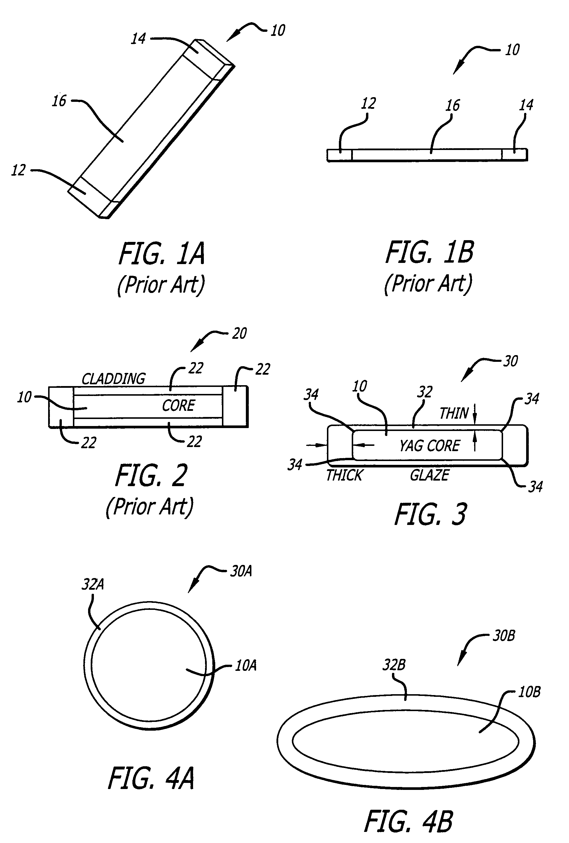
[0019]FIG. 1a is a perspective view of a conventional laser gain medium plate 10, and FIG. 1b is a side view of the conventional laser gain medium plate 10 of FIG. 1a. The laser gain medium plate 10 is comprised of a thin core plate having a rectangular cross-section and including two undoped input and output sections 12 and 14 and a doped central se...


PUM

PropertyMeasurementUnit
temperatureaaaaaaaaaa
interfacial thermal stressesaaaaaaaaaa
elastic moduliaaaaaaaaaa

Abstract

A glaze encapsulated solid-state laser component. The novel laser component includes a core and a cladding of ceramic glaze disposed on a surface of the core. In an illustrative embodiment, the core is fabricated from a laser gain medium and the cladding material is a multi-oxide eutectic ceramic glaze having a refractivity slighter lower than the refractivity of the gain medium, such that the glaze layer forms a step-index refractivity interface cladding that can effectively suppress parasitic oscillations in the core gain medium. The glaze cladding can be applied by coating the core with the glaze and then firing the glaze coated core, or by fabricating pre-formed cladding strips from the ceramic glaze in a first firing cycle, mounting the pre-formed strips to the core, and then fusing the pre-formed strips to the core in a secondary firing cycle.

Description

BACKGROUND OF THE INVENTION[0001]1. Field of the Invention[0002]The present invention relates to solid-state laser technology. More specifically, the present invention relates to cladding techniques and materials for suppression of parasitic oscillations in solid-state laser oscillators and amplifiers.[0003]2. Description of the Related Art[0004]Recent advances in high-energy diode-pumped solid-state lasers have facilitated extensive developments in the architecture of laser components such as laserable slabs and rods. Solid-state laser slabs typically-include a thin planar solid-state gain medium (core plate) that is encapsulated by a solid crystal cladding. The core plate, primarily having a rectangular cross-section, is a key laser component affecting beam quality at high energy levels. Commercial laser slabs are typically comprised of single crystals, such as Yb:YAG (ytterbium doped yttrium-aluminum-garnet) and Nd:YAG (neodymium doped yttrium-aluminum-garnet), or nanocrystalline...

Claims


Application Information

Patent Timeline
Patent Type & Authority Patents(United States)
IPC IPC(8): H01S3/14C03C8/00H01S3/17
CPCH01S3/0612H01S3/0602H01S2301/02
Inventor USHINSKY, MICHAELBETIN, ALEXANDER A.GENTILMAN, RICHARDHOGAN, PATRICK K.
Owner RAYTHEON CO
Why Eureka
Try Eureka