Zoom lens and image-pickup apparatus

a zoom lens and image-picking technology, applied in the field of new zoom lenses and image-picking apparatuses, can solve the problems of luminous power shortage, reduced light-receiving area of individual photoelectric transducers, and increased noise effect, so as to achieve high-quality images and reduce the thickness of the second lens group

Inactive Publication Date: 2010-04-27
SONY CORP
View PDF10 Cites 7 Cited by
  • Summary
  • Abstract
  • Description
  • Claims
  • Application Information

AI Technical Summary

Benefits of technology

[0019]Therefore, according to the present invention, the thickness of the second lens group is reduced so that compatibility between the miniaturization and the offering high-performance is possible.
[0022]Therefore, in the zoom lens according to the present invention, the thickness of the second lens group is reduced so that compatibility between the miniaturization and the offering high-performance is possible. The image-pickup apparatus according to the present invention can be miniaturized while high-quality images can be obtained by using the zoom lens according to the present invention.

Problems solved by technology

However, a problem has arisen in that the light-receiving area of the individual photoelectric transducer is reduced due to the high-integration and the miniaturization, so that the noise effect is increased along with the reduction in electric output.
That is, when the exit pupil position of the lens system comes close to the light-receiving element, the angle of the principal beam arriving at the light-receiving element defined by the optical axis is increased so that the angle of the off-axial luminous flux toward the picture periphery to the optical axis is further increased so as not to arrive on the light-receiving element, resulting in luminous power shortage.
In the PNPP four-zoom lens group mentioned above, since only one lens group having negative refracting power exists, the negative distortion has been difficult to be corrected at the wide-angle end.
As the variator is only the second lens group, the refracting power has been difficult to be reduced for obtaining a predetermined variable power ratio, so that the negative distortion needs to be corrected with the other lens groups.
However, in the second lens group serving as a variator, the off-axial luminous flux passes through off the optical axis at the wide angle end while the on-axial luminous flux passes through in a spreading state at the telescopic end, so that the eccentric coma is liable to develop even by the micro-eccentricity produced during manufacturing, resulting in a problem of the optical quality deterioration.
Hence, as in Japanese Unexamined Patent Application Publication No. 08-160299, when the convex lens surface of the lens arranged nearest to the object of the second lens group opposes an aperture diaphragm, the eccentric coma is liable to develop in the picture periphery at the wide angle end by the micro-eccentricity produced during manufacturing, and because of three single lenses, the eccentric coma is liable to develop in the picture center at the telescopic end by the micro-eccentricity produced during manufacturing, resulting in the difficulty in maintaining predetermined optical quality.
In the zoom lens disclosed in Japanese Unexamined Patent Application Publication No. 11-52236, because a diffraction optical element is included, although the number of lenses is small, the diffraction has been changed by the micro-eccentricity produced during manufacturing, so that the correction state of aberrations is varied, resulting in a problem of the difficulty in obtaining a predetermined optical performance.
Hence, a barrel structure and an adjustment method in those the eccentricity produced during manufacturing is suppressed as much as possible are required, so that the barrel structure and the adjustment operation have been complicated, resulting in a high increase in cost.
In the zoom lens disclosed in Japanese Unexamined Patent Application Publication No. 2002-36554, because the convex lens surface arranged adjacent to the object of the biconcave lens having an aspheric surface opposes the aperture diaphragm, the coma due to the eccentricity and developed in the picture periphery is largely varied, so that the optical quality has been deteriorated due to the slight assemble error during manufacturing, resulting in a problem of the difficulty in obtaining stable optical quality.

Method used


Image

  • Zoom lens and image-pickup apparatus
  • Zoom lens and image-pickup apparatus
  • Zoom lens and image-pickup apparatus

Examples


embodiment 1

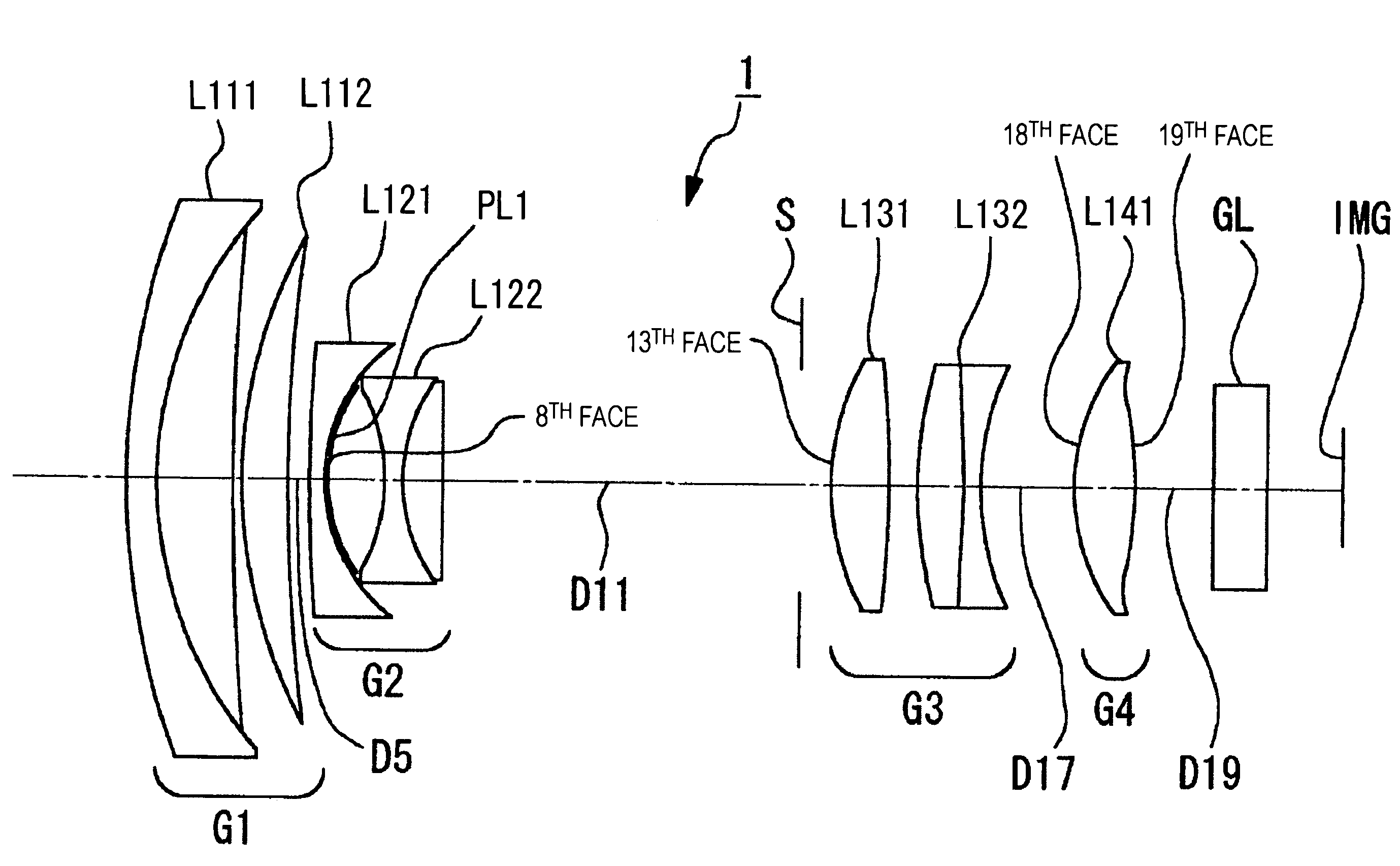
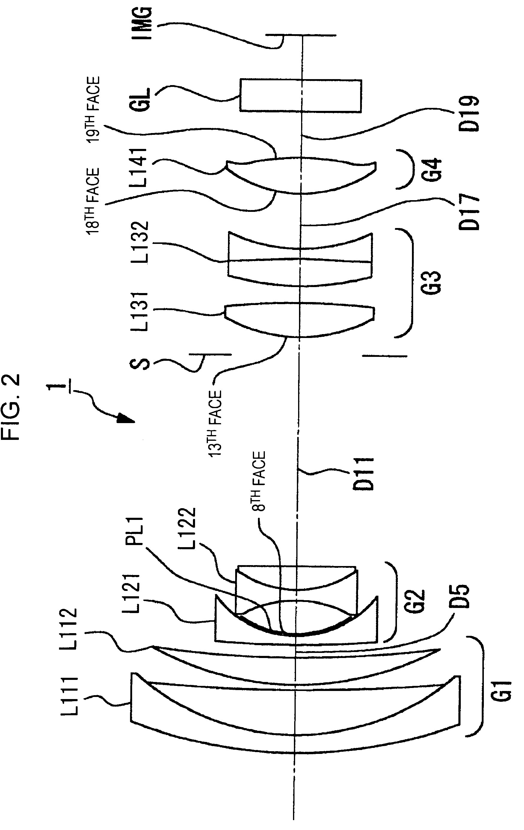
[0090]In the numerical embodiment 1, lens surfaces of 8th face, 13th face, 18th face, and 19th face are aspheric and aspheric factors are shown in Table 2.

[Table 2]

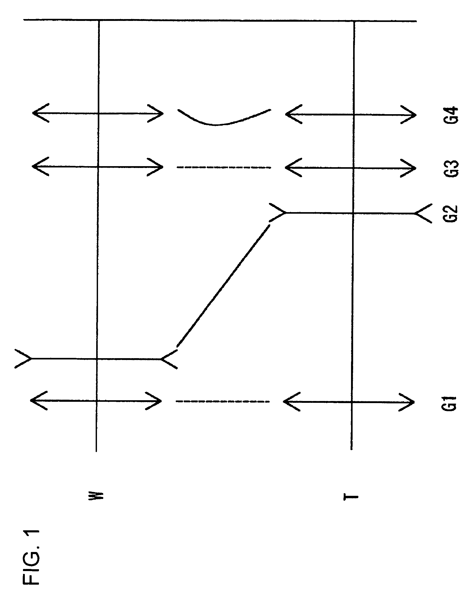
[0091]In the first embodiment 1, during the changing of lens positions, an axial interplanar space D5 between the first lens group G1 and the second lens group G2, an axial interplanar space D11 between the second lens group G2 and the aperture diaphragm S, an axial interplanar space G17 between the third lens group G3 and the fourth lens group G4, and an axial interplanar space D19 between the fourth lens group G4 and the protection glass GL are variable. Each variable axial interplanar space in the numerical embodiment 1 is shown in Table 3 with the focal length f.

[Table 3]

[0092]Table 4 below shows corresponding values to the conditional equations (1) to (4) in the numerical embodiment 1.

[Table 4]

[0093]FIGS. 3 to 5 show aberrations in an infinite-distance focusing state in the numerical embodiment 1; FIG. 3 shows aberra...

embodiment 2

[0099]In the numerical embodiment 2, lens surfaces of 8th face, 12th face, 19th face, and 20th face are aspheric and aspheric factors are shown in Table 6.

[Table 6]

[0100]In the second embodiment 2, during the changing of lens positions, the axial interplanar space D5 between the first lens group G1 and the second lens group G2, the axial interplanar space D11 between the second lens group G2 and the third lens group G3, an axial interplanar space G18 between the third lens group G3 and the fourth lens group G4, and an axial interplanar space D20 between the fourth lens group G4 and the protection glass GL are variable. Each variable axial interplanar space in the numerical embodiment 2 is shown in Table 7 with the focal length f.

[Table 7]

[0101]Table 8 below shows corresponding values to the conditional equations (1) to (4) in the numerical embodiment 2.

[Table 8]

[0102]FIGS. 7 to 9 show aberrations in an infinite-distance focusing state in the numerical embodiment 2; FIG. 7 shows aber...

embodiment 3

[0108]In the numerical embodiment 3, lens surfaces of 8th face, 13th face, 18th face, and 19th face are aspheric and aspheric factors are shown in Table 10.

[Table 10]

[0109]In the third embodiment 3, during the changing of lens positions, the axial interplanar space D5 between the first lens group G1 and the second lens group G2, the axial interplanar space D11 between the second lens group G2 and the aperture diaphragm S, the axial interplanar space G17 between the third lens group G3 and the fourth lens group G4, and an axial interplanar space D19 between the fourth lens group G4 and the protection glass GL are variable. Each variable axial interplanar space in the numerical embodiment 3 is shown in Table 11 with the focal length f.

[Table 11]

[0110]Table 12 below shows corresponding values to the conditional equations (1) to (4) in the numerical embodiment 3.

[Table 12]

[0111]FIGS. 11 to 13 show aberrations in an infinite-distance focusing state in the numerical embodiment 3; FIG. 11 ...


PUM


Abstract

To provide a zoom lens capable of achieving stable optical quality by inhibiting an effect of assemble errors during manufacturing. A zoom lens includes a positive first lens group G1, a negative second lens group G2, a positive third lens group G3, and a positive fourth lens group G4, which are arranged from an object side in that order, and during variation in lens position from a wide angle end state to a telescopic end state, G1 and G3 are fixed, G2 is moved toward an image side, G4 moves so as to compensate fluctuations in image-surface position due to the shift of G2, and an aperture diaphragm S is fixed adjacent to the object side of G3, etc. G2 includes a negative meniscus lens L21 with a concave surface opposing the image side and a cemented lens L22 of a biconcave lens and a positive lens with a convex surface opposing the object side, which are arranged from the object side in that order, and the negative meniscus lens is a compound lens of a glass lens and a resin lens PL formed adjacent to the image side of the glass lens, the lens surface adjacent to the image side of the resin lens is aspheric, and the conditional equation (1) below is satisfied:n2>1.75,   (1)where n2 is the average refractive index of glass constituting G2.

Description

TECHNICAL FIELD[0001]The present invention relates to new zoom lenses and image-pickup apparatuses, and in detail relates to a zoom lens suitable for cameras photo-detecting with an image-pickup element, such as a video camera and a digital still camera, and an image-pickup apparatus using the zoom lens.BACKGROUND ART[0002]A recording method has been known in that the luminous power of an object image formed on a surface of an image-pickup element by the image-pickup element using a photoelectric transducer, such as a CCD (charge coupled device) and a CMOS (complementary metal-oxide semiconductor), is converted into an electric output by the photoelectric transducer so as to record it.[0003]Along with the recent technological progress in micro-fabrication technique, a central processing unit (CPU) is speeded up and memory media are highly integrated, so that high-capacity image data, which have been difficult to handle, have got to be processed at high-speed. Also, light-receiving e...

Claims


Application Information

Patent Timeline
Patent Type & Authority Patents(United States)
IPC IPC(8): G02B15/14
CPCG02B15/173G02B27/646G02B15/144113G02B13/009G02B3/0087G02B3/0062G02B1/041G03B17/12G02B2003/0093H04N23/55
Inventor OHTAKE, MOTOYUKIARITA, SHINICHI
Owner SONY CORP
Why Eureka
Try Eureka