
Vacuum cell for optical components

a vacuum cell and optical component technology, applied in the field of vacuum cell for optical components, can solve the problems of loss of transparency, deformation of optical quality of polished surfaces of hygroscopic crystals, and problems such as the loss of transparency

Active Publication Date: 2010-05-25
COHERENT INC
View PDF8 Cites 3 Cited by
  • Summary
  • Abstract
  • Description
  • Claims
  • Application Information

AI Technical Summary

Benefits of technology

The solution effectively protects the crystal from water vapor and contamination, maintaining beam quality and conversion efficiency while minimizing the risk of damage from laser radiation, with a reliable and long-lasting seal that reduces the need for additional retaining hardware.

Problems solved by technology

This can be quite problematic for a high-precision optical component made from a hygroscopic material.
The optical quality of polished surfaces of a hygroscopic crystal tends to degrade with extended exposure to water vapor due to gradual dissolution at the surfaces as water is taken up by the material.
Such degradation is commonly characterized by a loss of transparency associated with increased scatter from a roughened surface or, in extreme cases, with distortion of the surface figure.
Such effects generally degrade both the conversion efficiency and the frequency-converted laser beam quality obtainable from a degraded harmonic conversion crystal.
This approach can be quite effective but has the drawback of requiring the presence of a controlled heat source and the need to provide power to the heat source
However, such coatings are frequently associated with other problems, particularly for coatings dense and thick enough to provide an effective barrier.
Edge-chipping, cracking, or crazing can often be observed to occur in such barrier coatings as a result of temperature cycling.
In addition, such coatings may also degrade or be damaged more quickly than bulk materials, particularly as a result of extended exposure to intense laser light.
Prior-art vacuum-tight window sealing techniques can be problematic for a variety of reasons.
Mechanical methods tend to rely upon bulky, flanged window retaining structures that apply and maintain compressive forces sufficient to deform a sealing gasket situated between a window and a mating surface.
Brazing or soldering techniques not only require selective metallization of window surfaces but also involve highly elevated temperatures unlikely to be tolerated by a delicate optical component situated in close proximity to a seal.
Adhesives such as cured epoxies can be used to attach and seal windows but are prone to out-gassing, particularly during curing but also over extended time periods.
Out-gassing products can contaminate the component enclosed in the cell.
Yet another problem may be encountered in damage to windows of an enclosure from exposure to laser radiation.
This is a problem in particular when the cell contains a crystal that is generating ultraviolet radiation.

Method used


Image

  • Vacuum cell for optical components
  • Vacuum cell for optical components
  • Vacuum cell for optical components

Examples


Embodiment Construction

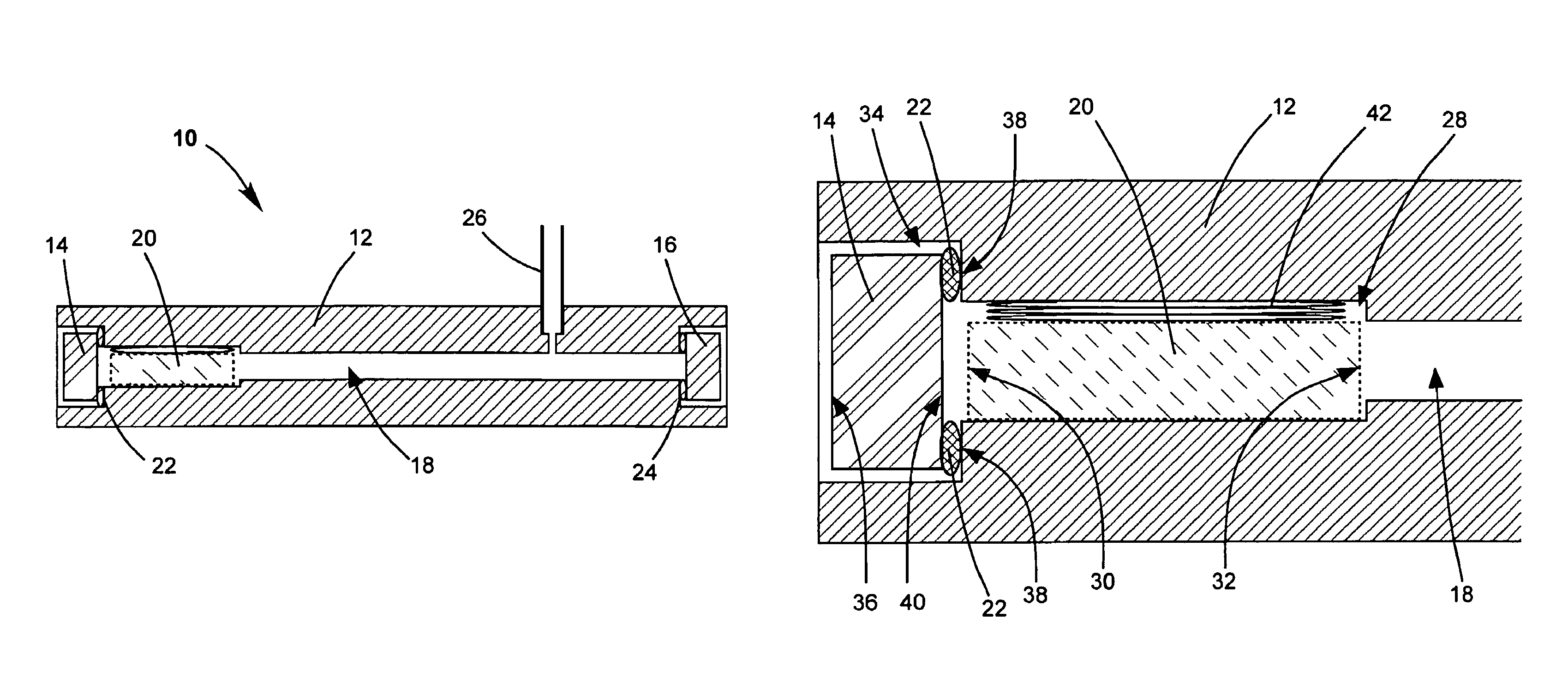
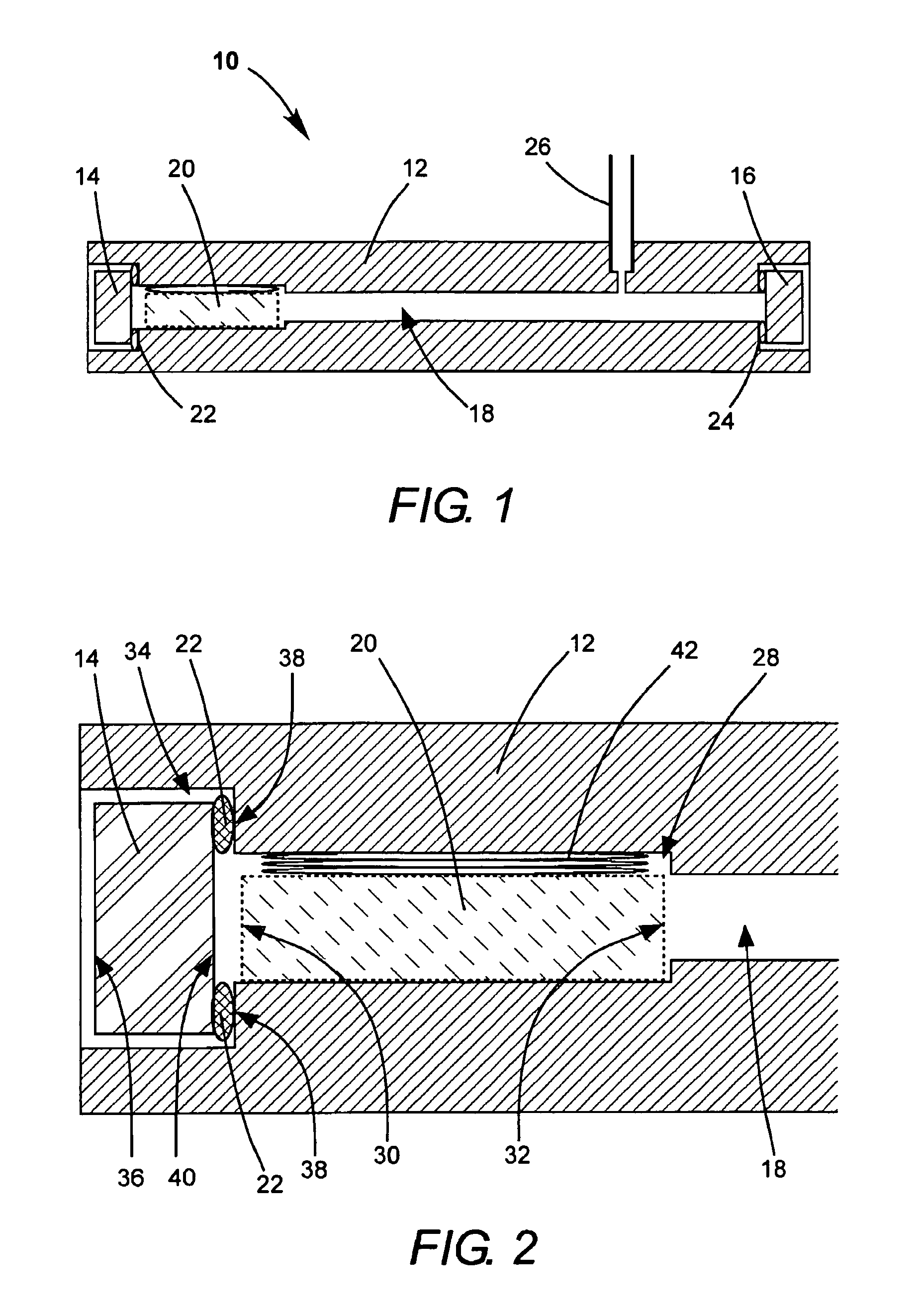
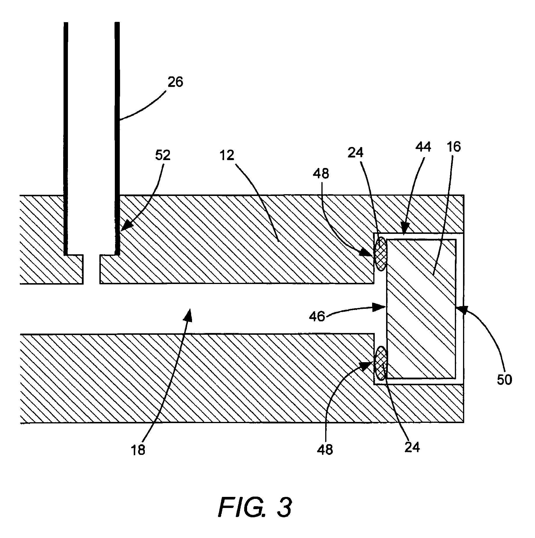
[0022]Referring now to the drawings, wherein like features are designated by like reference numerals, FIG. 1 is a cross-section view schematically illustrating one preferred embodiment 10 of a vacuum cell in accordance with the present invention. Cell 10 includes an elongated, rigid enclosure-body 12, preferably of a metal such as kovar, stainless steel, or non-anodized aluminum or an alloy thereof. Optical access to the cell is provided through an optical input window 14 and an optical output window 16. Body 12 is completely penetrated by a through-passage 18 to allow propagation of light through cell 10 and particularly through an optical component 20 enclosed therein, here, an optically nonlinear crystal. By way of example, optically nonlinear crystal 20 may be a crystal of as potassium KDP, BBO, LBO, CBO or CLBO. A characteristic common to these particular materials is that all are water-soluble, and in general they are hygroscopic, especially CBO and CLBO. Input window 14 is lo...


PUM

PropertyMeasurementUnit
wavelengthaaaaaaaaaa
lengthaaaaaaaaaa
lengthaaaaaaaaaa

Abstract

A moisture sensitive optically nonlinear crystal is enclosed in a hermetically sealed elongated vacuum cell. The vacuum cell has an input window at one end and an output window at an opposite end providing optical access to the crystal by a laser beam. The windows are attached to the cell by cold-formed, indium-metal ram-seals. In an example of the cell in which the crystal is arranged to generate UV radiation from the laser beam, the output window is located at a sufficient distance from the crystal that the flux of UV radiation incident on the output window is below the damage threshold of the window for the UV radiation.

Description

PRIORITY CLAIM[0001]This application claims priority from prior provisional application Ser. Nos. 60 / 814,737, filed Jun. 19, 2006, which are incorporated herein by reference.TECHNICAL FIELD OF THE INVENTION[0002]The present invention relates in general to packaging of environmentally sensitive optical components for minimizing environmental degradation of such components. The invention relates in particular to minimizing degradation of optically nonlinear crystals used for laser wavelength conversion.DISCUSSION OF BACKGROUND ART[0003]Optical components fabricated from optically nonlinear crystals are commonly employed for wavelength conversion in laser systems. A well-known example of wavelength conversion is the process of harmonic generation, wherein an appreciable fraction of the power contained in a beam of laser light having a particular wavelength and a corresponding fundamental optical frequency is shifted to a different wavelength, specifically a wavelength associated with a...

Claims


Application Information

Patent Timeline
Patent Type & Authority Patents(United States)
IPC IPC(8): G02B7/02G02B3/12G02B7/00
CPCG02B27/0006G02F1/0107G02F1/3501G02F2001/3505G02F1/37G02F1/3505G02B1/11
Inventor GHORBANI, ARASHFRANK, PETEREDMOND, R. IAN
Owner COHERENT INC
Learn More