System and method for detecting and quantifying changes in the mass content of liquid storage containers

a liquid storage container and mass content technology, applied in fluid tightness measurement, instruments, machines/engines, etc., can solve the problems of high detection threshold, easy to see the difficulty in preventing and detecting leakage, and insufficient mitigation of duties or liabilities of responsible parties, so as to reduce the detection threshold and preserve industrial and environmental resources.

Active Publication Date: 2010-06-22
MASS TECH
View PDF21 Cites 3 Cited by
  • Summary
  • Abstract
  • Description
  • Claims
  • Application Information

AI Technical Summary

Benefits of technology

[0019]In view of the foregoing, it is an object of the present invention to provide a storage tank leak detection apparatus with a very low detection threshold that may be used in an efficient manner thereby preserving industrial and environmental resources.
[0020]It is another object of the present invention to provide an apparatus for safe storage tank leak detection.
[0021]It is another object of the present invention to provide an apparatus for precise storage tank leak detection.

Problems solved by technology

That is, storage tank owners are willing to invest huge sums of money in both the maintenance and inspection of such tanks.
As one could imagine, there are a wide range of problems associated with maintaining storage tank integrity, particularly with above ground storage tanks.
Given the enormous dimensions of above ground tanks, the corrosive products contained within the tanks, the incredible mass of the stored product, and the extreme weather conditions the tanks are subjected to, it is plain to see that above ground storage tank leaks are an all-to-common problem.
Given the limited number of systems capable of meeting the EPA's underground storage tank leak detection threshold and the added difficulties associated with above ground tanks, the difficulty in protecting against and detecting leaks is easily seen.
However, the recognized difficulty in preventing storage tank leaks does not mitigate the duties or liabilities imposed on responsible parties.
Tremendous environmental and economic consequences and the threat of litigation and clean up costs associated with storage tank leaks force responsible parties to invest large sums of money in the maintenance and inspection of the tanks.
Tank inspections are costly with respect to the amount of money spent, the danger presented to the inspectors and the environment, and production downtime.
In fact, these inspections often remove a tank from service for more than one month.
The threat of liability also forces responsible parties to spend money unnecessarily for the maintenance of these tanks.
Currently, responsible parties are, in some countries, being incarcerated as a direct result of storage tank leaks.
These leaks have contaminated surrounding ground water, some of which serves as drinking water for local residents.
Each day the shuttered facilities remain inoperative adds to an already tremendous amount of money lost.
Presently available leak detection systems lack detection thresholds low enough to detect leaks down to permissible upper leakage limits for above ground storage tanks
Storage tank leak detection systems are known in the art; however, these products are fraught with problems.
The present systems are imprecise, or provide erroneous data for any or all of reasons including: the consistency of the soil acting as the tank's foundation, the temperature stratification of the in-tank product, extraneous noise sources, thermal expansion of the tank's contents, water table level, previous soil contamination, and / or tank shell dynamics.
Further, some detection devices can only be used when the storage tank is empty, and no known system or method ensures a comprehensive inspection of the tank.
The most common form of such a system is “vacuum box testing”; however, this system is intended only for weld joints and is not usually applied to the entire tank bottom.
Magnetic flux floor scanning is also used, but is not effective at examining the area of the floor surface close to the surface walls or where there are physical obstructions.
Ultrasonic detection is used, but this is only effective for small areas of the surface.
Gas detection is also used, but the types of materials stored in the tank can obstruct this method.
However, even large volume changes produce only small level changes, as the cross-sectional area of the liquid surface in these tanks is very large.
This, combined with differential expansion and temperature change of the stored liquid and its vapor, make this type of detection system inconsistent and very nearly worthless.
Present mass measurement leak detection systems in the art are limited by tank shell variations resulting from temperature effects on tank shell plating.
As such, known mass measurement detection systems are only sensitive enough to be used in smaller tanks, typically underground storage tanks.

Method used


Image

  • System and method for detecting and quantifying changes in the mass content of liquid storage containers
  • System and method for detecting and quantifying changes in the mass content of liquid storage containers
  • System and method for detecting and quantifying changes in the mass content of liquid storage containers

Examples


Embodiment Construction

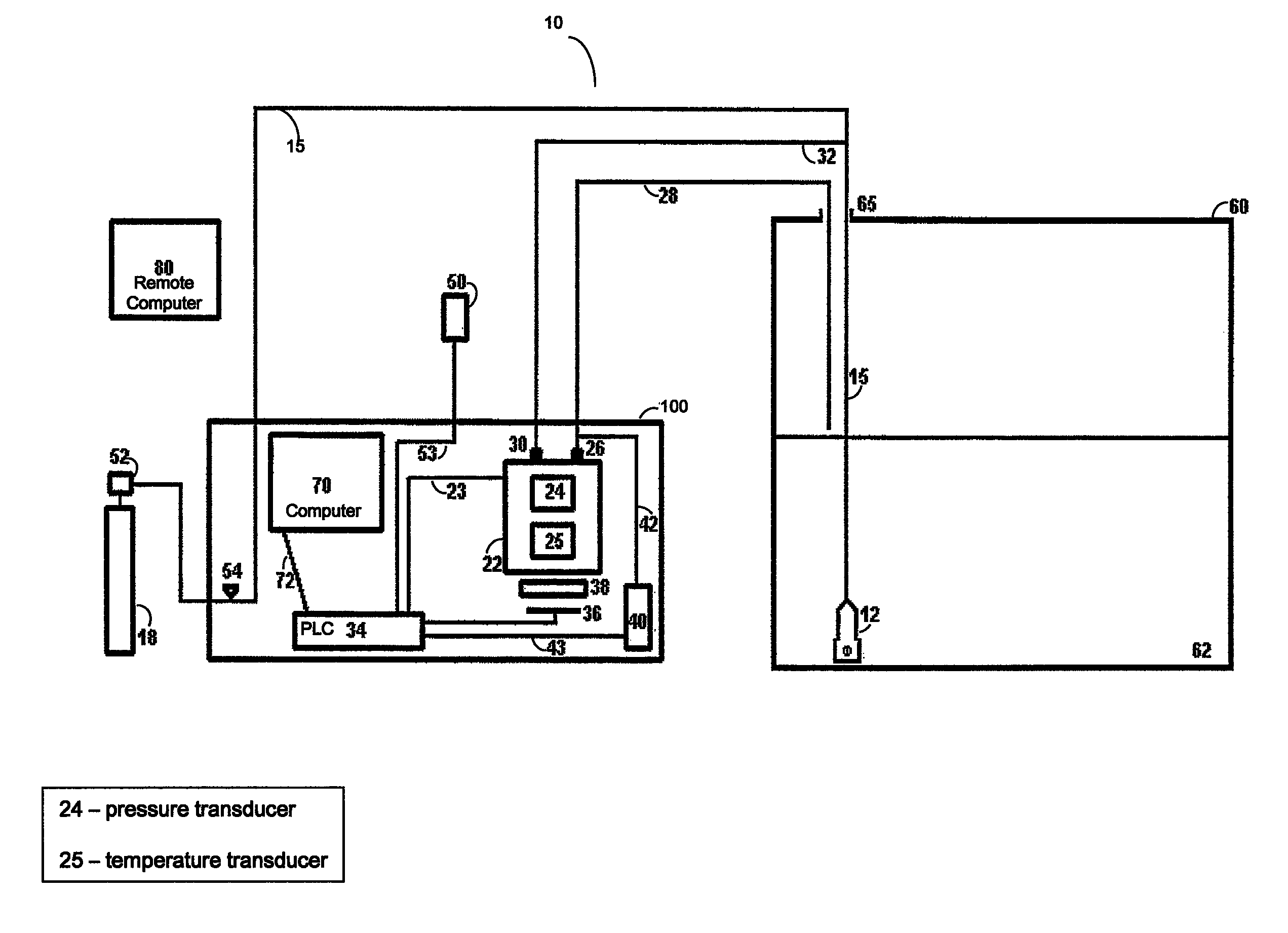
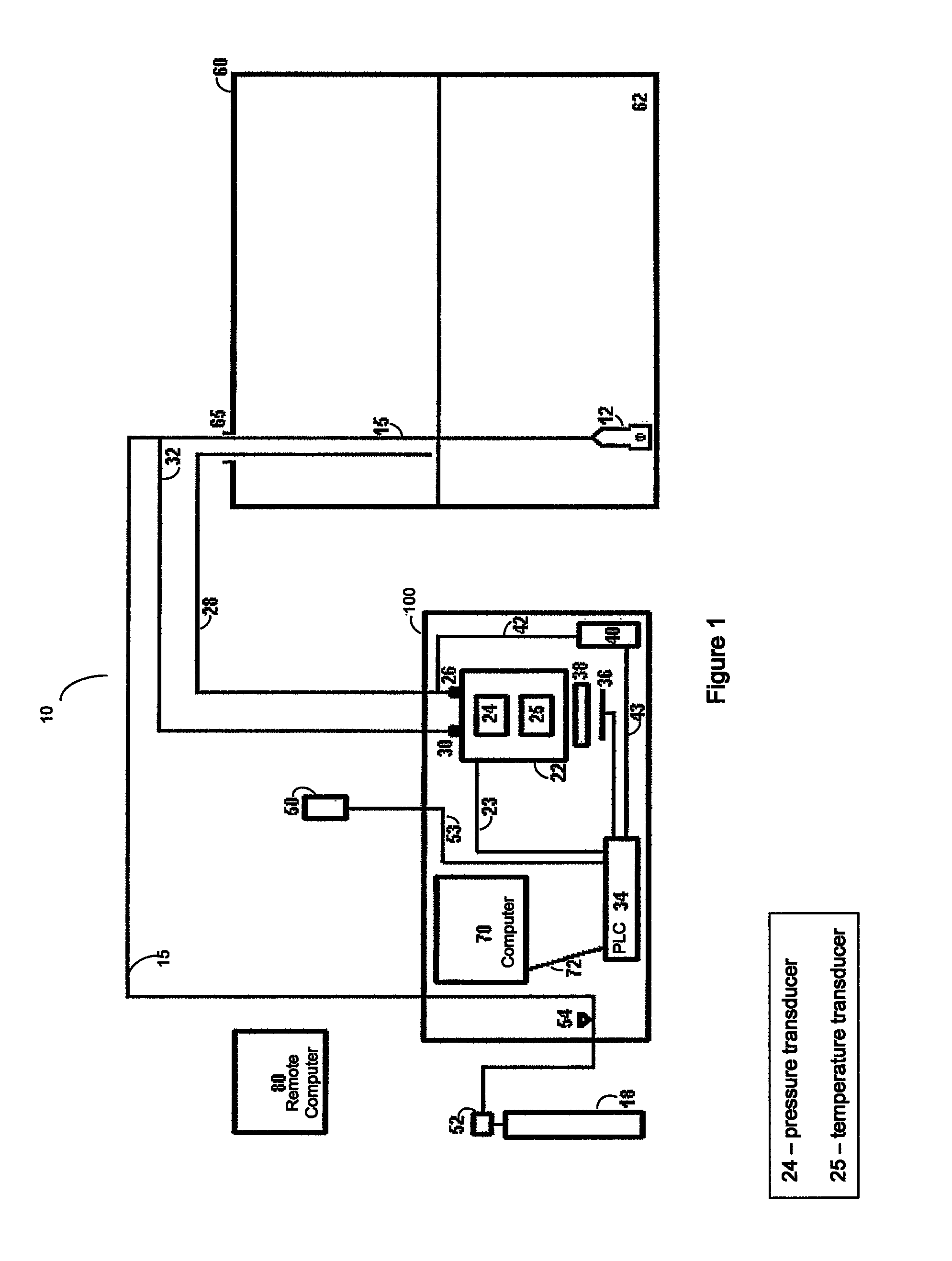
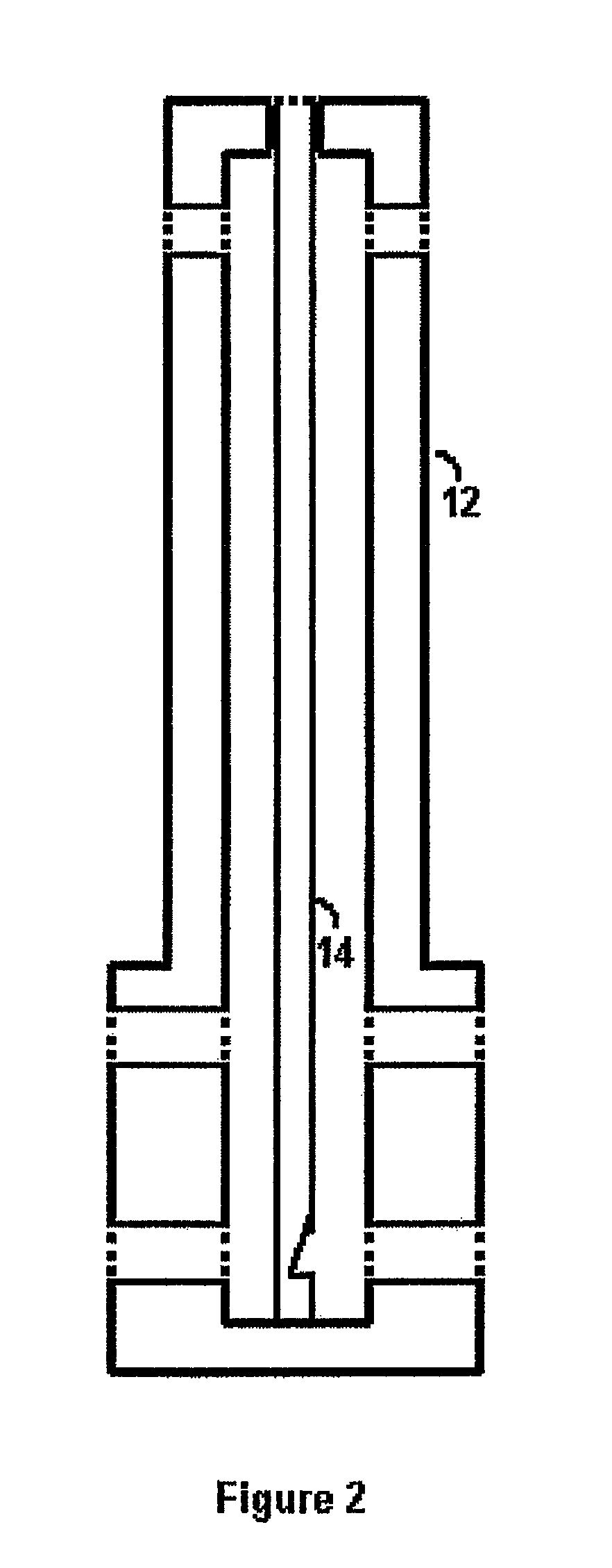
[0079]In the drawings and the description that follows, FIGS. 1 and 2 generally depict a preferred configuration and constituency of a storage tank leak detection system according to the present invention, which system is generally designated by the reference number 10.

[0080]The preferred embodiment of the present invention includes an inert gas pressure reduction 52 and flow rate regulator 54 which provide a clean and steady supply of an inert gas, such as nitrogen, from a compressed cylinder 18 to an in-tank bubbler 12 via bubbler tube 15.

[0081]The in-tank bubbler 12, which is placed substantially at the bottom of a to-be-evaluated storage tank 60, releases inert gas bubbles in a consistent manner with minimal pressure variation. The minimum inert gas pressure required to consistently form and release bubbles at the bottom of the tank's contents serves as a proxy for the hydrostatic pressure at the bottom of the tank.

[0082]The formation and release of inert gas bubbles in a consis...


PUM


Abstract

A storage tank leak detection system, including a quartz crystal type pressure transducer held at a constant temperature, a bubbler-based pressure sensor for reporting tank bottom pressure measurements to the transducer, a fluid surface measurement apparatus to report liquid surface pressure to the transducer, atmospheric pressure measuring apparatus, and a computing system for, based on data reported by all components, effecting data correction (corrected for atmospheric and container physical variations during data gathering) and regression techniques to yield data indicative of changes, if any, in mass content of a liquid storage container, such as a surface storage tank for petroleum and other chemicals.

Description

CROSS REFERENCE TO RELATED APPLICATIONS[0001]This is a continuation-in-part application with respect to Patent Cooperation Treaty International Application PCT / US2005 / 016930 filed on May 13, 2005, which is a continuation-in-part of Patent Cooperation Treaty International Application PCT / US2004 / 021704 filed on Jul. 7, 2004, both of which designated the U.S. and are incorporated by reference in their entireties.BACKGROUND OF THE INVENTION[0002]1. Field of the Invention[0003]The present invention is directed towards a method and apparatus for providing a safe, precise, and cost-effective storage tank leak detection system and more particularly, to a method and apparatus wherein the containment integrity of a storage tank is determined by mass measurements of the stored product.[0004]2. Background Information[0005]Storage tanks play a vital role in today's economy. The economy, on a global scale, depends on the proper function of these tanks as they are prevalent in several industries a...

Claims


Application Information

Patent Timeline
Patent Type & Authority Patents(United States)
IPC IPC(8): G01M3/32
CPCG01M3/3263G01M3/3245
Inventor WOLFORD, JIMMYWOLFORD, BERNIELOCKERD, CLARKSLAUGHTER, RICKY
Owner MASS TECH
Why Eureka
Try Eureka