Aerosol collection apparatus and methods

a collection apparatus and anthrax technology, applied in the field of aerosol collection apparatus and methods, can solve the problems of insufficient detection limits of anthrax bacilli, inhalation of low but lethal doses of anthrax or other biological warfare [bw] aerosol agents, and inability to detect anthrax bacilli effectively, etc., to achieve low pressure, high air flow, and low power consumption

Inactive Publication Date: 2010-08-03
ZAROMB SOLOMON +2
View PDF8 Cites 13 Cited by
  • Summary
  • Abstract
  • Description
  • Claims
  • Application Information

AI Technical Summary

Benefits of technology

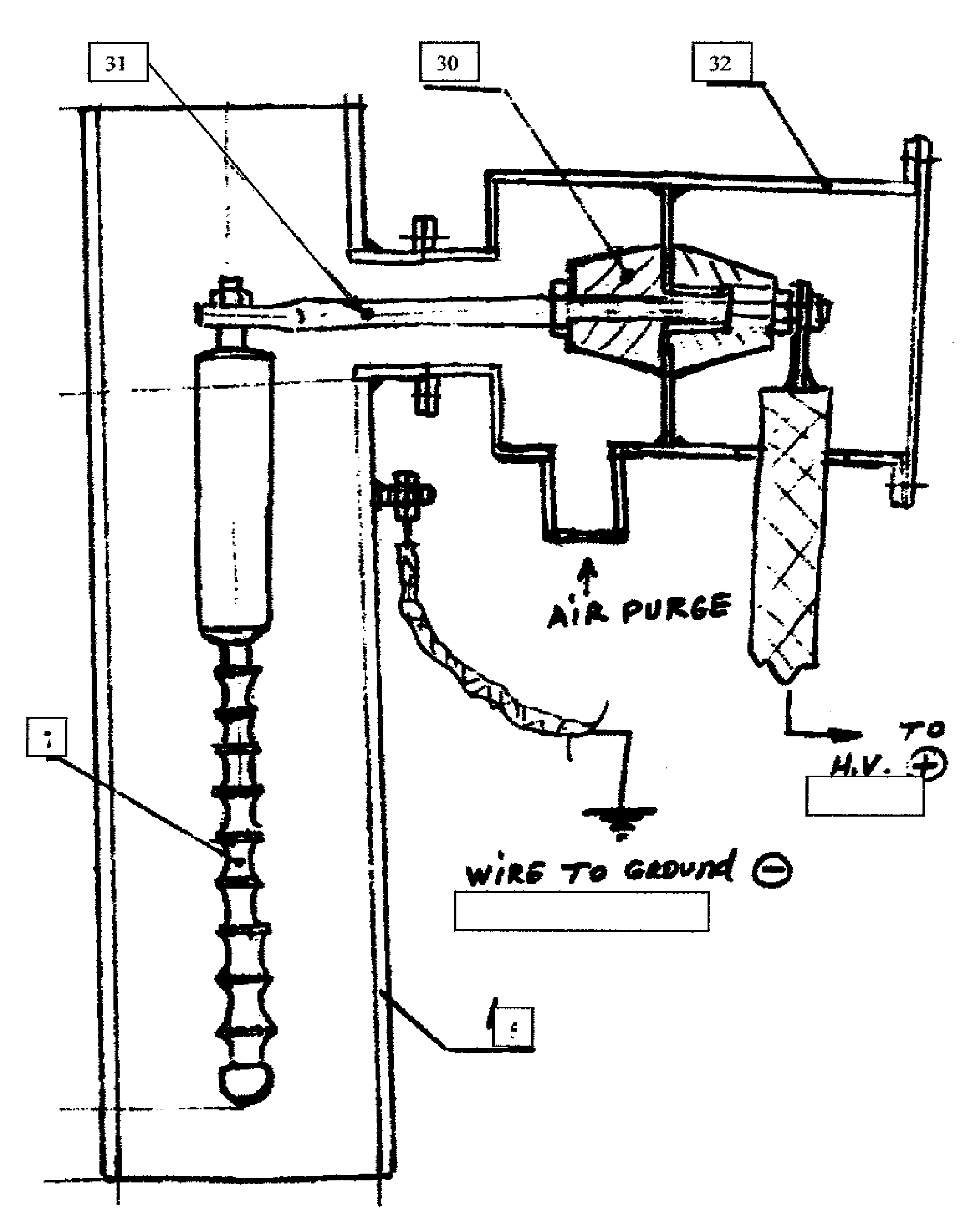
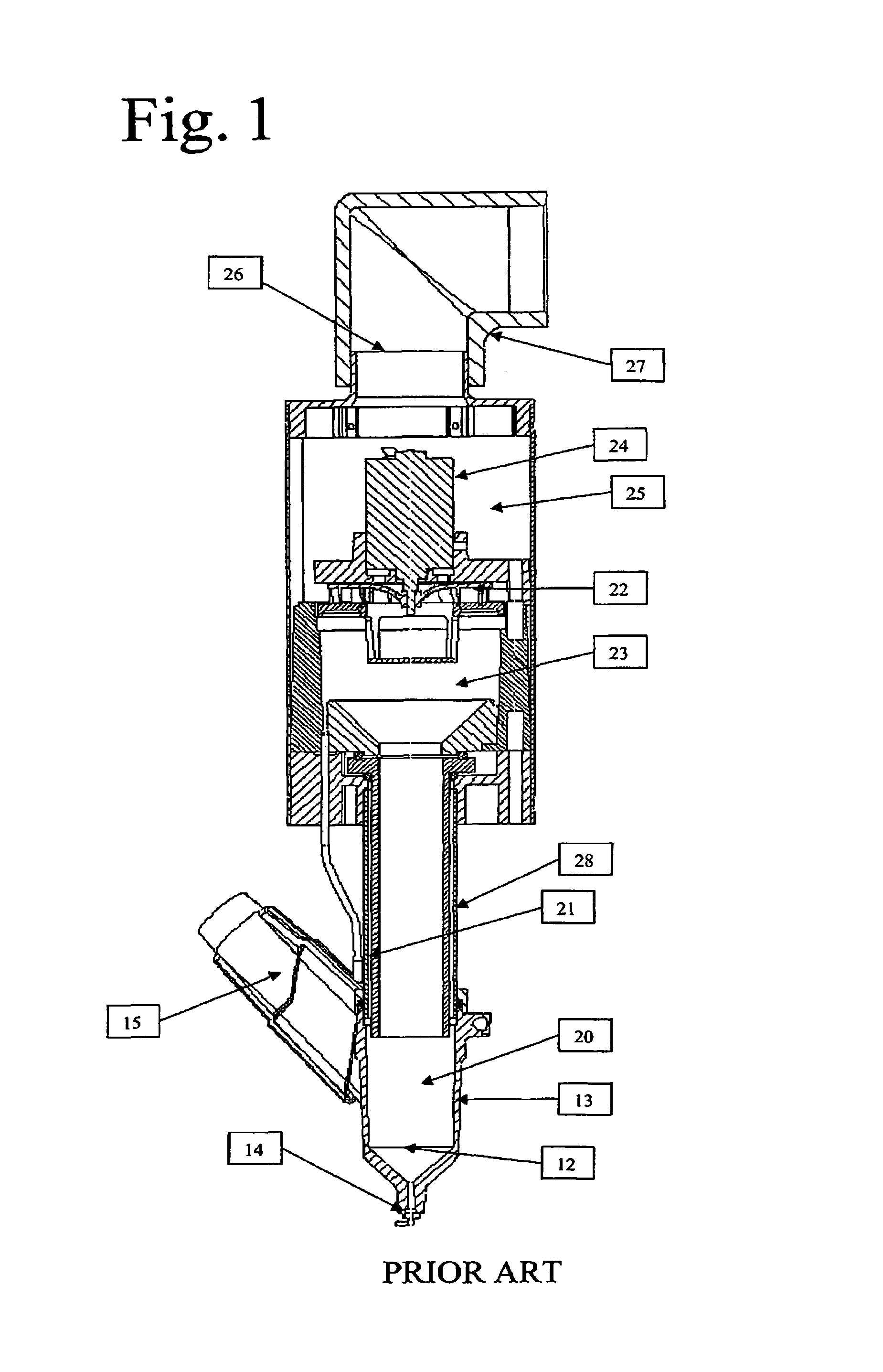
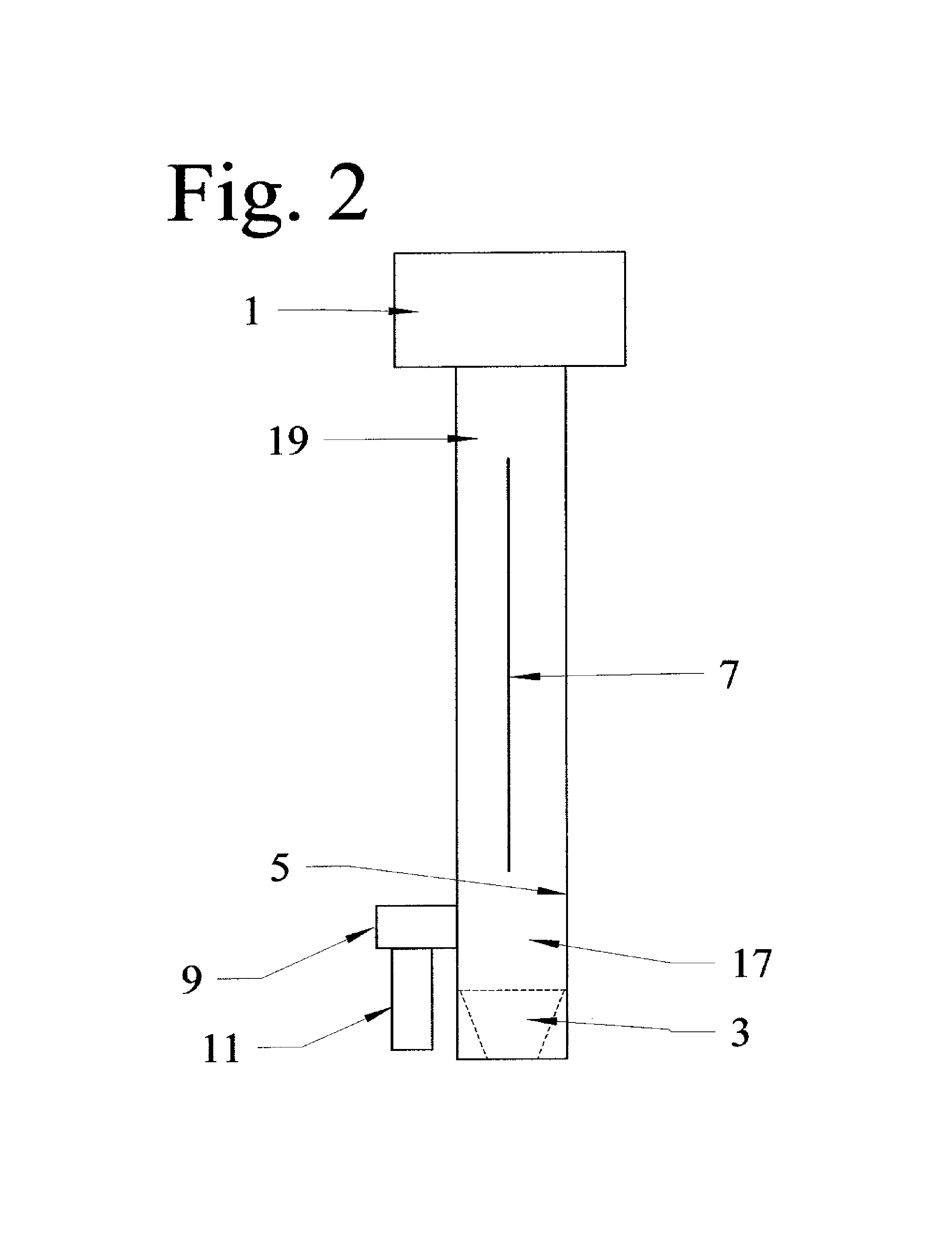
[0020]Briefly, the invention consists of effectuating modifications in the basic configuration of the PHTLAAS of Pat. No. 6,565,811 so as to convert it into an EP-based air sampler. These modifications consist of replacing the glass sampling tube of the PHTLAAS by an electrically conductive collector electrode tube, inserting a wire- or rod-shaped high-voltage discharge electrode co-axially with the collector electrode, and modifying the air intake so that it is designed and disposed to yield a high air flow through the sampler at a low pressure drop and low power consumption. Upon turnin

Problems solved by technology

With subsequent use of the same apparatus for the collection of respirable particles, the term “absorption” became inappropriate, as the collected particles may remain suspended in the carrier liquid without being dissolved therein.
However, recent incidents of bio-terrorisms have revealed serous shortcomings of these collectors.
When these were used in conjunction with immunoassay-based test strips, the resulting effective detection limit for anthrax bacilli was far above the known dangerous or lethal concentrations, so that inhalation of low but lethal doses of anthrax or other biological warfare [BW] aerosol agents could have been easily overlooked.
Cyclones and most inertial separation devices are intrinsically very inefficient at captu

Method used


Image

  • Aerosol collection apparatus and methods
  • Aerosol collection apparatus and methods
  • Aerosol collection apparatus and methods

Examples


example 1

[0045]For collection efficiency measurements, we use suspended 1-micron fluorescent beads obtained from Duke Scientific Corporation, Palo Alto, Calif. 94303. The fluorescent beads permit direct measurements with the aid of a fluorometer of the amounts of particles captured in the collection medium. The concentrations of particles in the sampled air are measured with the aid of a reference filter and their variations within out 3,000-liter test chamber are monitored with an APS [Aerodynamic Particle Sizer] instrument.

[0046]The described system was assembled, tested, and fine-tuned as follows:

[0047]1. The lower inlet portion of the WEP unit had a plastic inlet connected through a 3″ diameter pipe to the ultrasonic humidifier and test chamber.

[0048]2. Using a redesigned rotor, the power required to circulate air through the WEP sampler to and from the test chamber at a rate of 510 l / min was only 8.4 watts [2 amps at 4.2 volts].

[0049]3. The following test procedure was worked out:

[0050]...


PUM


Abstract

Apparatus and methods for detecting the presence of an airborne chemical or biological analyte utilise:a substantially gas- and liquid-impermeable container; means for introducing a substantially analyte-free collection liquid into said container; means for rapidly sampling ambient air and transferring said analyte therefrom into said collection liquid, said sampling means comprising an air intake means and and an air venting means; and-means for removing from said container an analyte-enriched collection liquid; wherein said volume of air passes through a substantially horizontal air inlet and upwardly through a substantially vertical collector electrode tube with means for applying an electric field between said tube and a co-axial spiked wire- or rod-shaped discharge electrode.

Description

CROSS REFERENCE TO RELATED APPLICATIONS[0001]This is a non-provisional application of provisional application number 60 / 481,184, filed Aug. 6, 2003, which is related to my U.S. Pat. No. 5,328,851, 6,087,183, and 6,565,811 and to its U.S. patent applications Ser. Nos. 08 / 377,966 [filed Jan. 25, 1995] and 09 / 611,744 [filed Jul. 7, 2000] now U.S. Pat. Nos. 6,762,068B1 and 6,642,057B1. The disclosures of all of said applications and patents are incorporated herein by reference.”BACKGROUND OF INVENTION[0002]This invention relates to improved apparatus and methods for detecting harmful substances, whether airborne or grounded, whether biological or chemical, which may pose an immediate or long term hazard to human life or health.[0003]The afore-cited patents and co-pending applications, disclose apparatus and methods for collecting various contaminants—including vapors and particles, chemical or biological—from a large volume of air into a small volume of carrier liquid, so as to permit o...

Claims


Application Information

Patent Timeline
IPC IPC(8): B01L3/00
CPCG01N1/2202
Inventor ZAROMB, SOLOMONMARTELL, DENNIS J.RAY, ISAAC
Owner ZAROMB SOLOMON
Why Eureka
Try Eureka