Plate type heat exchanger and method of manufacturing the same

a heat exchanger and plate type technology, applied in the field of plate type heat exchangers, can solve the problems of increasing the size and functionality of computer devices, increasing the difficulty of achieving effective cooling methods, and increasing the size of computer devices, so as to achieve the effect of bringing the heat easily and reliably

Active Publication Date: 2010-08-10
NAKAMURA SEISAKUSHO KK
View PDF5 Cites 10 Cited by
  • Summary
  • Abstract
  • Description
  • Claims
  • Application Information

AI Technical Summary

Benefits of technology

[0016]An object of the present invention is to provide a plate-type heat exchanger comprising heat-medium-guiding grooves of extremely small widths that have the necessary capillary force to move a heat medium from a condensing part to an evaporating part without affecting the set alignment or the like.
[0017]Another object of the present invention is to provide a method for manufacturing a plate-type heat exchanger comprising heat-medium-guiding grooves of extremely small widths that have the necessary capillary force to move a heat medium from a condensing part to an evaporating part without affecting the set alignment or the like.
[0018]Still another object of the present invention is to provide a plate-type heat exchanger comprising a structure in which a heat medium can easily be poured into a hollow part having heat-medium-guiding grooves of extremely small widths formed in the inner peripheral surface portion, and a specific vacuum state can be easily established in the hollow part.

Problems solved by technology

Recently, computer devices have been rapidly becoming smaller and more highly functional.
As these devices become more highly functional, greater amounts of heat are generated from the semiconductor elements and integrated circuits in these devices, and effective cooling methods are becoming problematic with respect to making computer devices even smaller and even more highly functional.
However, in most cases, since these grooves are integrally formed in the container by extrusion, the grooves will necessarily increase in width, and sufficient capillary force will not be obtained.
As a result, when the alignment of the heat pipe is set so that the position of the evaporating part is higher than the condensing part, the capillary force is insufficient, and the working fluid that has been returned to the liquid phase by the condensing part can no longer be returned to the evaporating part.
Therefore, the flow rate of working fluid is reduced, the amount of working fluid in the evaporating part gradually becomes insufficient, and eventually the evaporating part dries up and the heat-generating components can no longer be cooled.
The temperature of the heat-generating components thereby rises excessively, causing reductions or failures in the performance of the heat-generating components, which are semiconductor elements and integrated circuits and the like.
It has been difficult to form grooves of such width by using commonly adopted conventional extrusion techniques.
Particularly, extrusion is impossible with a copper material having good thermal conductivity.
However, it has been difficult to form grooves of such precise width when these materials are machined using a forming operation other than extrusion.
In addition, wires or the like are sometimes inserted into the grooves to supplement the capillary force, but the using such auxiliary members to enhance capillary force leads to increased costs.
Moreover, the auxiliary members that enhance capillary force are disposed nonuniformly in the minute grooves, causing the cooling capacity to become nonuniform and leading to problems in terms of reliability.
This vacuum state leads to problems in that the working fluid sometimes boils, and it is difficult to pour in the working fluid.
In cases in which the joining surfaces of the main body member and the lid member are sealed to achieve an airtight structure in the hollow part, problems are encountered in that the sealing operation for achieving a vacuum state in the vacuum furnace is very difficult to accomplish.
Therefore, there is a possibility that the working fluid will be insufficient, the evaporating part will not contain enough working fluid, the heat-generating components will not be adequately cooled, and the temperature of the heat-generating components will increase excessively, leading to reductions or failures in the performance of heat-generating components such as semiconductor elements and integrated circuits.
Also, since the joining surfaces of the main body member and the lid member are not completely sealed, severe problems may occur, such as an increase in the degree of vacuum in the hollow part, an inability of the working fluid to smoothly change phases or move smoothly, inadequate thermal transfer, and a marked reduction in the cooling capacity of the heat pipe.

Method used

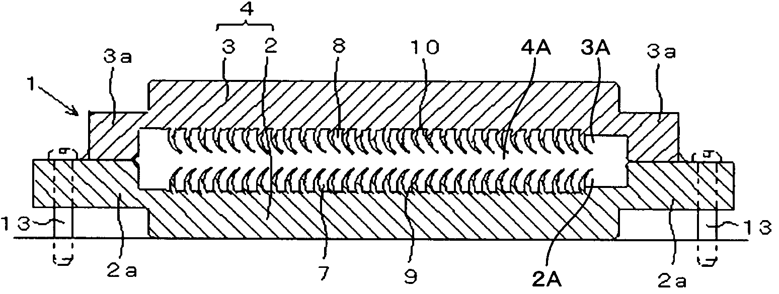
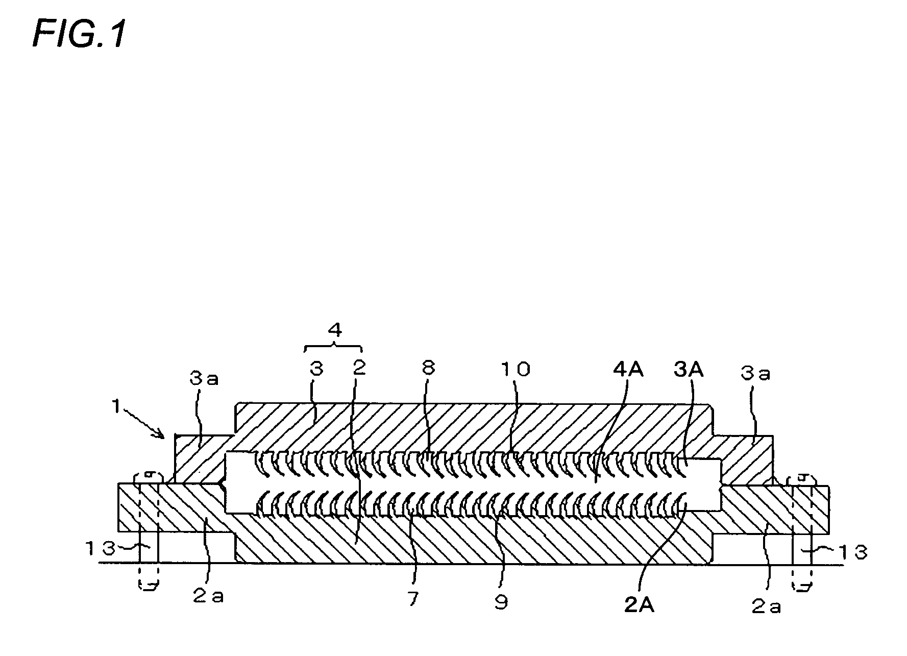
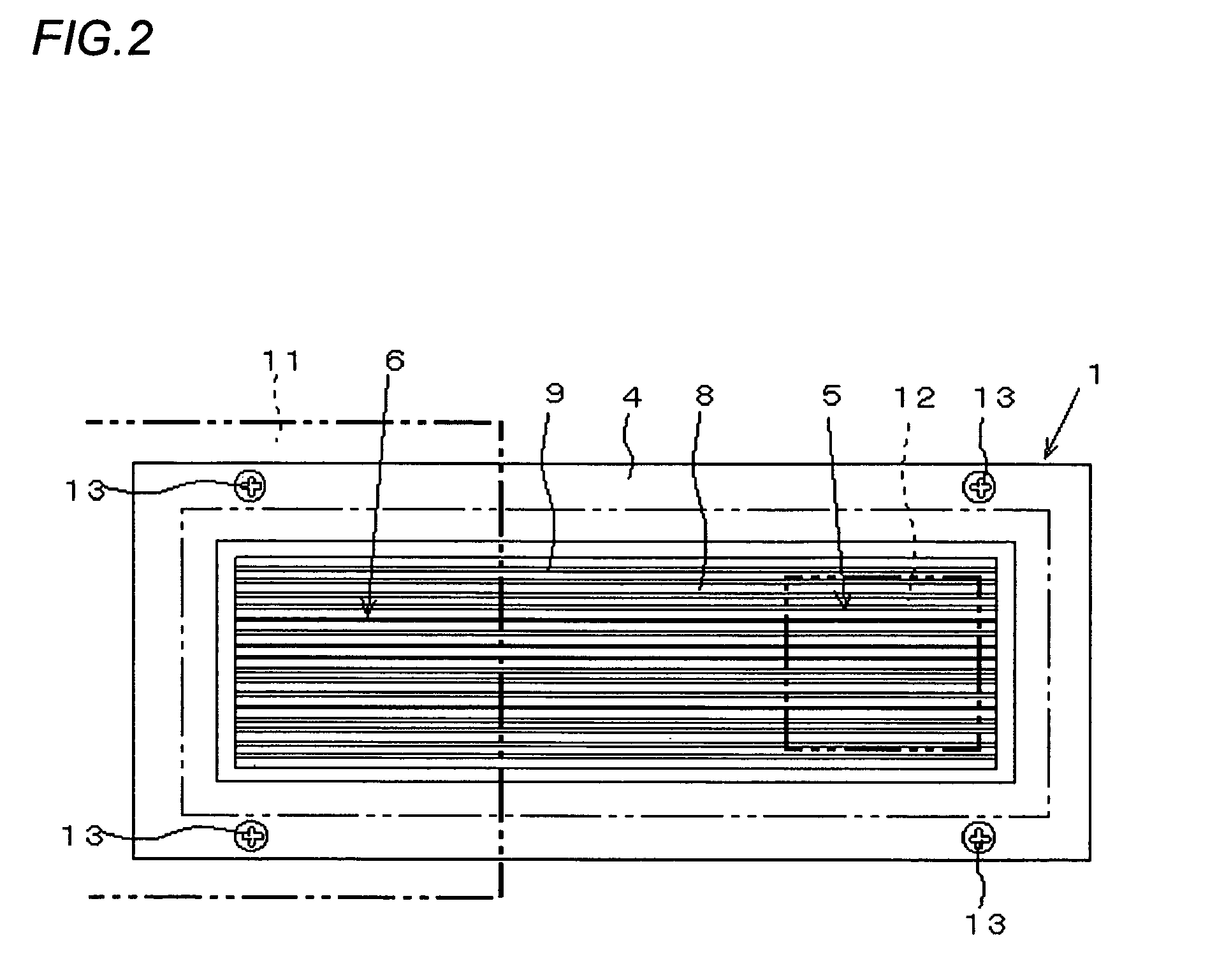

Image

  • Plate type heat exchanger and method of manufacturing the same
  • Plate type heat exchanger and method of manufacturing the same
  • Plate type heat exchanger and method of manufacturing the same

Examples


embodiment 1

Modifications of Embodiment 1

[0132]A hoop-type metal plate made of aluminum, an aluminum alloy, copper, a copper alloy, stainless, steel, or the like can be used instead of the metal plate 20. Specifically, a hoop-type metal plate 50 is mounted while being positioned on a die (not shown) as shown in FIG. 9. One surface of the hoop-type metal plate 50 is then carved out by the blade 31 of the above-described carving tool 30 to form fins 60 of a specific height in an upright manner.

[0133]The hoop-type metal plate 50 is then moved by a specific pitch and is positioned and fixed in place on the die. After the blade 31 of the carving tool 30 is brought into contact at a position that is upstream of the machined surface 51 and that produces a specific carving margin, the carving tool 30 is moved at a specific angle towards the other side of the hoop-type metal plate 50 to a position that produces a specific pitch, and carves out the hoop-type metal plate 50 to form the next thin fin 60 in...

embodiment 2

Modifications of Embodiment 2

[0168]FIG. 21 depicts a modification of the communication hole for communicating the hollow part 104A of the plate-type heat pipe 101 with the exterior. In the plate-type heat pipe 101(1) depicted in FIG. 21(A), a concave groove 115 (communication groove) is formed in the connected surface (joined surface) of the bottom container 102 formed on the outer edge of the sealing member 103(1), and a communication hole 116 is formed in the concave groove 115 by joining the sealing member 103(1) with the outer edge portion of the bottom container 102. The concave groove 115 can be formed when the sealing member 103 is press-worked. A concave groove 115 may also be formed near each of two corners at opposite ends of a diagonal on the sealing member 103. Furthermore, the concave groove 115 may be formed on the side of the bottom container 102, or a groove may be formed on both of the outer edge portions of the sealing member 103(1) and the bottom container 102.

[01...


PUM


Abstract

A method for manufacturing a plate-type heat exchanger in which a heat medium is sealed in a hollow part of an airtight structure formed in the interior of a plate-like container, and the heat medium is moved by capillary force from a condensing part to an evaporating part in the hollow part along heat-medium-guiding grooves formed in the container's inside surface portions that face the hollow part; wherein a plastic workable metal plate of specific thermal conductivity is prepared; a carving tool is used to repeatedly carve out a surface portion of the metal plate at specific intervals along the surface portion, forming a plurality of plate-like fins; and a plurality of grooves formed between these fins is used as heat-medium-guiding grooves. A plate-type heat exchanger is obtained which comprises extremely small heat-medium-guiding grooves that have the necessary capillary force to move the heat medium from the condensing part to the evaporating part without affecting the set alignment or other such characteristics.

Description

FIELD OF THE INVENTION[0001]The present invention relates to a plate-type heat exchanger that is suitable for use as a flat heat pipe or a vapor chamber that is used to cool a semiconductor chip, an integrated circuit board, or another heat generator; and to a method for manufacturing the same.RELATED ART[0002]Recently, computer devices have been rapidly becoming smaller and more highly functional. As these devices become more highly functional, greater amounts of heat are generated from the semiconductor elements and integrated circuits in these devices, and effective cooling methods are becoming problematic with respect to making computer devices even smaller and even more highly functional.[0003]Various cooling systems have been proposed to cool high-output, high-integration chips and the like. Focus has been given to liquid-cooled heat exchangers, typified by heat pipes, as such cooling systems. As a liquid-cooled heat exchanger, a heat pipe may be shaped as a round heat pipe or...

Claims


Application Information

Patent Timeline
Patent Type & Authority Patents(United States)
IPC IPC(8): F28F3/14F24H3/00F24H9/02F28F17/00F28F1/20
CPCF28D15/0233F28D15/046
Inventor MIYAHARA, HIDEYUKI
Owner NAKAMURA SEISAKUSHO KK
Why Eureka
Try Eureka