
Charge perturbation detection system for DNA and other molecules

a detection system and charge technology, applied in the field of electrochemical molecular detection, can solve the problems of direct, label-free electrochemical detection methods, and achieve the effect of reducing the number of dna and other molecules

Active Publication Date: 2010-08-31
THE BOARD OF TRUSTEES OF THE LELAND STANFORD JUNIOR UNIV
View PDF21 Cites 117 Cited by
  • Summary
  • Abstract
  • Description
  • Claims
  • Application Information

AI Technical Summary

Benefits of technology

"The invention is a method and device for detecting enzymatically catalyzed DNA synthesis by measuring the change in surface charge of a metal electrode. The device can detect the reaction of a reactant with a target molecule, such as DNA or RNA, by measuring the current generated during the reaction. The device can be used in a variety of applications, such as DNA sequencing or analysis of phosphorylation. The method involves using a high overpotential metal electrode to detect the charge perturbation caused by the removal of a proton from the DNA molecule during phosphodiester bond formation. The device can be fabricated using microfluidics and the same mixture of reactants can be delivered to each electrode. The technical effects of this invention include improved accuracy and sensitivity in detecting DNA synthesis and a simplified method for measuring the phosphorylation state of a substrate."

Problems solved by technology

1, 2) However, direct, label-free electrochemical detection methods are not available.

Method used


Image

  • Charge perturbation detection system for DNA and other molecules
  • Charge perturbation detection system for DNA and other molecules
  • Charge perturbation detection system for DNA and other molecules

Examples


example 1

(FIG. 1): Schematic Diagram of Charge Perturbation Detection System

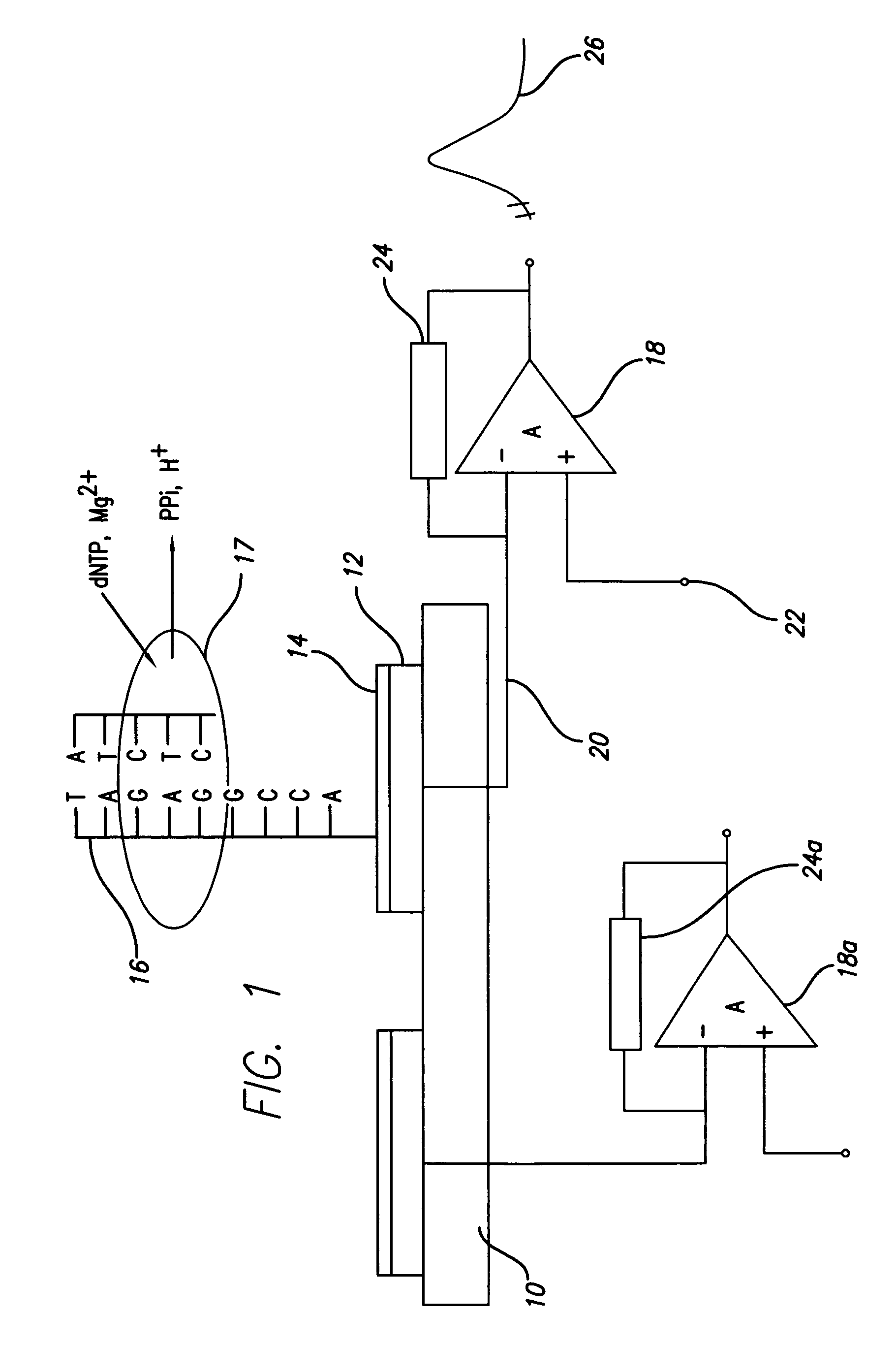
[0066]FIG. 1 is a schematic diagram of a device according to the present invention, with attached enzyme and substrate, showing the generation of ions and the detection circuitry. The device is formed on a substrate 10, by the attachment of a metal electrode 12, preferably of an oxidation resistant, high potential metal such as gold. A coating or insulation layer 14, may also be applied to the electrode 12. A template DNA strand 16 is attached to the electrode structure. A primer DNA strand is hybridized to the template DNA strand 16. Deoxynucleotide triphosphate (dNTP) and Mg2+ ions are added. Incorporation of the complementary dNTP releases inorganic pyro phosphate (PPi) and H+ ions (protons). A DNA polymerase complex is illustrated at 17 and ion movement is shown relative to the enzymatic reactions, i.e. dNTP, MG2+ in and PPi and H+ out.

[0067]As described below, the charge perturbation in the vicinity of the elect...

example 2

(FIG. 2): Template Orientation and Operation

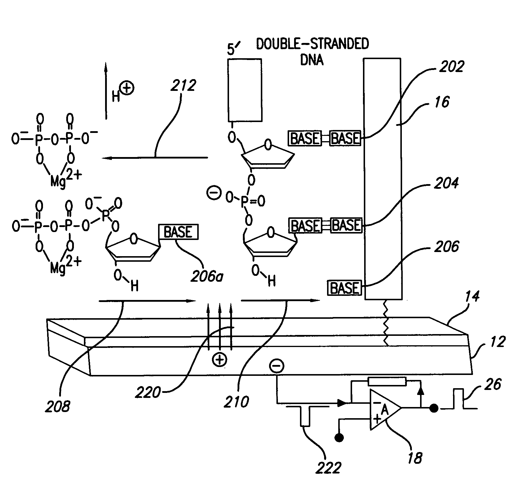
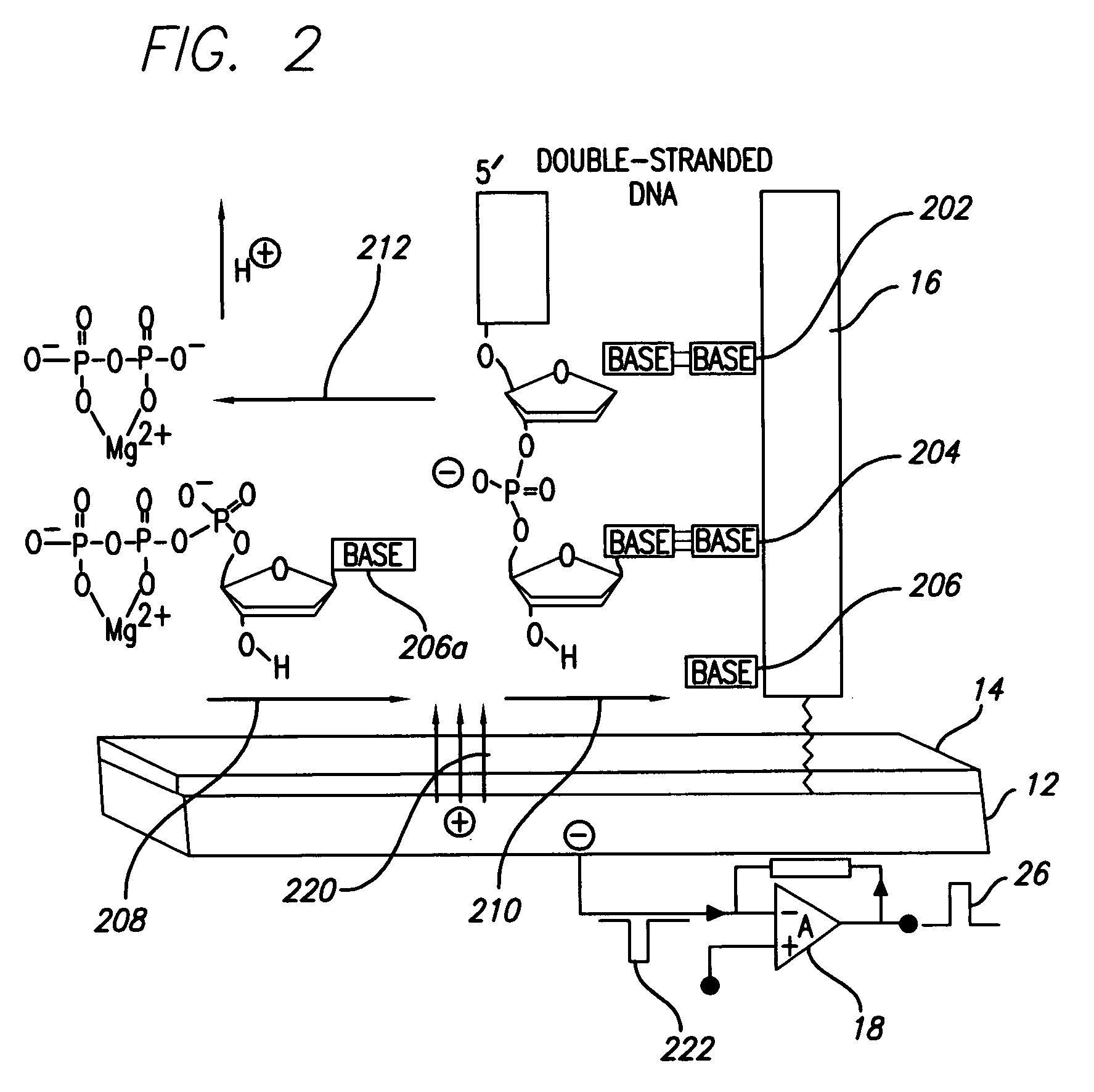
[0069]DNA polymerase catalyzes the incorporation of complementary nucleotides, resulting in perturbations of local electrical charge. Perturbations are based on interactions of system components and release of products of polymerization. These local perturbations of charge in solution induce a charge in coated polarazible gold Charge Perturbation Detection system (CPD) electrode. This event is detected as a transient current by voltage clamp amplifier, which compensates induced charge in the gold electrode. The high-impedance coating prevents faradaic current that could deteriorate the sensor and analytes. For measurements of electrical activity of CPD electrode was used Axopatch 200B voltage clamp amplifier, but in principle any voltage-clamp amplifier can be used. Voltage command was kept at steady 0 mV holding potential, but because no faradaic current is present the voltage command can be kept on different holding potentials and can be...

example 3

(FIG. 3): Analysis of Signals

[0073]If the addition of individual dNTPs is performed sequentially, then nucleotide sequence peaks will appear as shown in a sequence poly-gram (FIG. 3). The individual detected signal is shown in FIG. 3A and FIG. 3C. If the addition of dNTPs is performed with a mix of all nucleotides then a run-off polymerization signal is detected (FIG. 3C). This signal can be then analyzed and multiple nucleotide bases can be determined by the shape of the curve, which will vary in response to the particular nucleotide incorporated.

[0074]In FIG. 3A, the addition of a dGTP binding to a C nucleotide in the template is shown. The spikes at the beginning of the signal are caused by dispensation disturbance and initial diffusion of dGTP solution and are easily filtered out. With no measurable delay after dispensation, current rises to a peak of ˜400 picoamps (pA) within ˜50 milliseconds (ms), rapidly decreases to ˜50 pA, and then shows a further, slower transient increase...


PUM

PropertyMeasurementUnit
currentaaaaaaaaaa
currentaaaaaaaaaa
feature sizeaaaaaaaaaa

Abstract

Methods and apparatus for direct detection of chemical reactions are provided. In a preferred embodiment, electric charge perturbations of the local environment during enzyme-catalyzed reactions are sensed by an electrode system with an immobilized target molecule. The target molecule is preferably DNA. The charge perturbation caused by the polymerase reaction can uniquely identify a DNA sequence. The polymerization process generates local perturbations of charge in the solution near the electrode surface and induces a charge in a polarazible gold electrode. This event is detected as a transient current by a voltage clamp amplifier. Detection of single nucleotides in a sequence can be determined by dispensing individual dNTPs to the electrode solution and detecting the charge perturbations. Alternatively, multiple bases can be determined at the same time using a mix of all dNTPs with subsequent analysis of the resulting signal. The initial enzyme attachment to the DNA molecule can be detected prior to polymerization, with electrode capacitance measurement using the same voltage-clamp amplifier. This technique and device may be adapted to other reaction determinations, such as enzymatic reactions, other electrode configurations, and other amplifying circuits.

Description

CROSS-REFERENCE TO RELATED APPLICATIONS[0001]This application claims priority from U.S. Provisional Patent Application No. 60 / 627,192 filed on Nov. 12, 2004, which is hereby incorporated by reference in its entirety.STATEMENT OF GOVERNMENTAL SUPPORT[0002]This invention was made with U.S. Government support under NIH Grants H200205 and 1R21AI059499-01. The U.S. Government has certain rights in this invention.REFERENCE TO SEQUENCE LISTING OR CD ROM[0003]NoneBACKGROUND OF THE INVENTION[0004]1. Field of the Invention[0005]The present invention relates to the field of electrochemical molecular detection, such as the detection of nucleic acid polymerization, by detection of a charged particle (e.g. proton) by means of a sensitive electrical circuit. The present invention has particular application to nucleic acid sequence detection and enzyme substrate modification detection.[0006]2. Related Art[0007]Rapid, sequence-specific DNA detection is essential for applications in medical diagnosti...

Claims


Application Information

Patent Timeline
Patent Type & Authority Patents(United States)
IPC IPC(8): C12Q1/68C12M1/36G01N15/06C07H21/04
CPCB82Y15/00B82Y30/00G01N27/3276G01N27/3275B82Y40/00C12Q1/6825
Inventor POURMAND, NADERDAVIS, RONALD W.KARHANEK, MILOSLAV
Owner THE BOARD OF TRUSTEES OF THE LELAND STANFORD JUNIOR UNIV
Learn More