Contact piece member, contactor and contact method

a contact piece and contact technology, applied in the direction of contacts, instruments, semiconductor/solid-state device details, etc., can solve the problems of reducing contact resistance, terminals cannot be arranged, and it is difficult to acquire a stable contact at a low-pressure pressur

Inactive Publication Date: 2010-09-14
SOCIONEXT INC
View PDF9 Cites 4 Cited by
  • Summary
  • Abstract
  • Description
  • Claims
  • Application Information

AI Technical Summary

Benefits of technology

[0054]A more specific object of the present invention is to provide a contact piece member which allows contact pieces being arranged at small pitch and achieves a contact surely with a small contact pressure and a contactor using such as contact piece member.

Problems solved by technology

For this reason, the contact area of the contact piece and the electronic part is increased by applying a large pressure between the both, thereby reducing the contact resistance.
Terminal intervals on a substrate side are larger than terminal intervals on a wafer side, which provides a restriction in terminal arrangement on a structure and cannot be dealt with the above-mentioned issue C. Additionally, there is a large restriction with respect to the issue D. Accordingly, there is a problem in that, for example, terminals cannot be arranged in an area array state or contact cannot be made simultaneously with adjacent semiconductor chips since a probe size is larger than a chip size.
Additionally, with respect to issue B, it is difficult to acquire a stable contact at a low-pressure.
Although it depends on a degree of bending, in order to arrange with a small pitch, adjacent needles (pins) become obstacles.
Additionally, in the structure in which needles are bent one after another, a manufacturing cost is very high.
There are Many Component Parts Such as a spring, a contact part and a barrel part accommodating the spring, and there is a limitation structurally in narrowing pitch.
With respect to the issue A, there is a limitation structurally in narrowing pitch.
That is, there is a limitation in reducing a winding diameter of the coil spring.
Moreover, with respect to the issue B, since there is no wiping action which can break an oxide film of an LSI terminal, a stable contact cannot be obtained at a low pressure.
Since a movable range of the contact electrode is small and it is a metal bump, it lacks flexibility.
Thus, there is a problem in that a contact defect of a low bump is caused due to variation in heights of adjacent bumps.
On the other hand, with respect to the issue D, since wirings extend as threading between contact electrodes, there is a limitation in a number of wirings.
Further, wirings of a membrane system do not progress in making multi-layered, and it is an extent in that wirings are provided on both sides of an insulating substrate.
With respect to the issue B, it is difficult to obtain a stable contact since deformation cannot be made if there is no pressure of a certain degree.
Additionally, there are other problems such that a heat resistance is low, a durability is low or the like.
Moreover, although a contact electrode can be produced with narrow pitch according to the method disclosed in the above-mentioned Patent Document 1, it is difficult to form the rubber stably with a minute shape.
Additionally, it is further difficult to form a metal or conductive film around the rubber.
Further, if a conductive film can be formed, the durability thereof will be a problem.
As mentioned above, according to the contact pieces of the conventional technology, it is not possible to provide a contactor, which solves all issues such as A) making minute terminals, B) making a low pressure, C) making a wide area and D) making area free, and has durability in a minute size.

Method used


Image

  • Contact piece member, contactor and contact method
  • Contact piece member, contactor and contact method
  • Contact piece member, contactor and contact method

Examples


second embodiment

[0105]Next, a description will be given of a contact piece member according to the present invention.

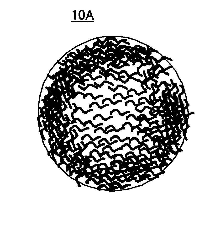
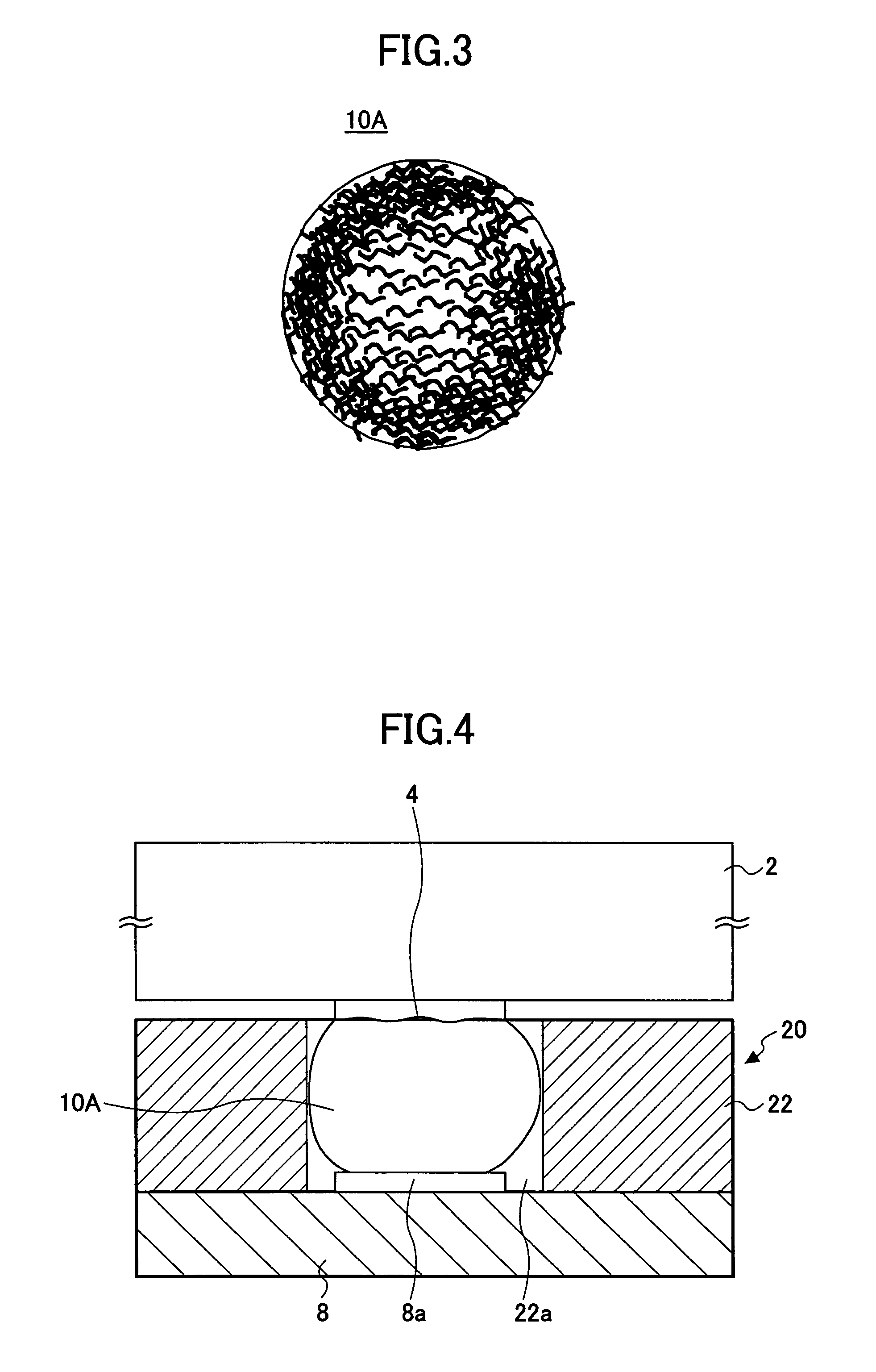
[0106]The contact piece member according to the second embodiment has the same structure as the contact piece members 10A and 10B according to the first embodiment of the present invention, that is, the structure shown in FIG. 3 or FIG. 6, but differs in a point that conductive fine particles are contained in an outer side cover film and an inner side gel or liquid.

[0107]As a material to form the contact piece member, there is used the material to form the above-mentioned contact piece members 10A and 10B added with electrically conductive particles. As the electrically conductive particles, metal particles or carbon particles, which are not corroded by hydrochloric acid or the like are suitable. Additionally, fine fibers of gold or carbon may be added as the electrically conductive particles.

[0108]A specific forming method is the same as the method of forming the above-mentioned con...

third embodiment

[0111]Next, a description will be given of a contact piece member according to the present invention.

[0112]In order to form a contact piece member having an inner part made of a gel having a low molecular density and a surface made of a thin film having a high molecular density, for example, a solution of sodium alginate as a mother material in which an electrically conductive material is contained is prepared. (The electrically conductive material may be the polymer material mentioned in the first embodiment, the electrically conductive fibers mentioned in the second embodiment, or a metal such as mercury exhibiting liquid phase below 150° C., or an alloy thereof.) This solution is dropped into a solution of calcium chloride or calcium lactate of 1 weight percent or more.

[0113]The molecular density of only the surface of the dropped contract piece material becomes high due to an osmotic pressure and a reaction with calcium within the solution of calcium chloride or calcium lactate ...


PUM


Abstract

In a contactor contact piece members can be arranged at a fine pitch, and a contact can be made surely by a small contact pressure. The contact piece members electrically connect an electronic part to an external circuit. The contact piece member is formed of an electrically conductive material in a generally spherical shape. A molecular density of a central part of the contact piece member is lower than a molecular density of a part near a surface. The electrically conductive material may include at least one of an electrically conductive fine particle, an electrically conductive fiber and an electrically conductive filler.

Description

CROSS-REFERENCE TO RELATED APPLICATION[0001]This application is a U.S. continuation application, filed under 35 USC 111(a) and claiming the benefit under 35 USC 120 and 365(c), of PCT application JP2004 / 018745 filed Dec. 15, 2004. The foregoing application is hereby incorporated herein by reference.BACKGROUND OF THE INVENTION[0002]1. Field of the Invention[0003]The present invention relates to an electric connection technique of electronic parts and, more particularly, to a minute contact piece for making electrical conduction by contacting an electrode of a semiconductor device represented by an LSI and a contact piece member used for such a contact piece.[0004]2. Description of the Related Art[0005]In recent years, with the demand for high performance and miniaturization of electronic equipments, there also is a demand for high performance and miniaturization of semiconductor devices, such as an LSI to be mounted on an electronic equipment. Accordingly, it is required for the semi...

Claims


Application Information

Patent Timeline
Patent Type & Authority Patents(United States)
IPC IPC(8): H01H1/02
CPCG01R1/06755H01L2924/0002H01L2924/00
Inventor MARUYAMA, SHIGEYUKINISHINO, TORU
Owner SOCIONEXT INC
Why Eureka
Try Eureka